Power distribution unit for wireless network topology and distribution method thereof

a technology of wireless network and power distribution unit, which is applied in the direction of network topologies, wireless commuication services, instruments, etc., can solve the problems of wds not being very efficient, wds expanding at breakneck speed, and the entire wireless network topology collapse, so as to improve the operation and convenience of the power distribution unit, and achieve the effect of convenient operation

Inactive Publication Date: 2014-11-27
LAI LI CHUN
View PDF5 Cites 3 Cited by
  • Summary
  • Abstract
  • Description
  • Claims
  • Application Information

AI Technical Summary

Benefits of technology

[0007]The present invention provides a power distribution unit for a wireless network topology and a distribution method thereof, and it is to enhance operations and convenience

Problems solved by technology

The market size of the wireless network is expanding at breakneck speed.
In addition, if one of the APs is offline or shutdown (power off), it may cause the collapses of the entire wireless network topology or loop, so that the entire domain communication causes problems.
Since present W

Method used


Image

  • Power distribution unit for wireless network topology and distribution method thereof
  • Power distribution unit for wireless network topology and distribution method thereof
  • Power distribution unit for wireless network topology and distribution method thereof

Examples


Embodiment Construction

[0032]Following preferred embodiments and figures will be described in detail so as to achieve aforesaid objects.

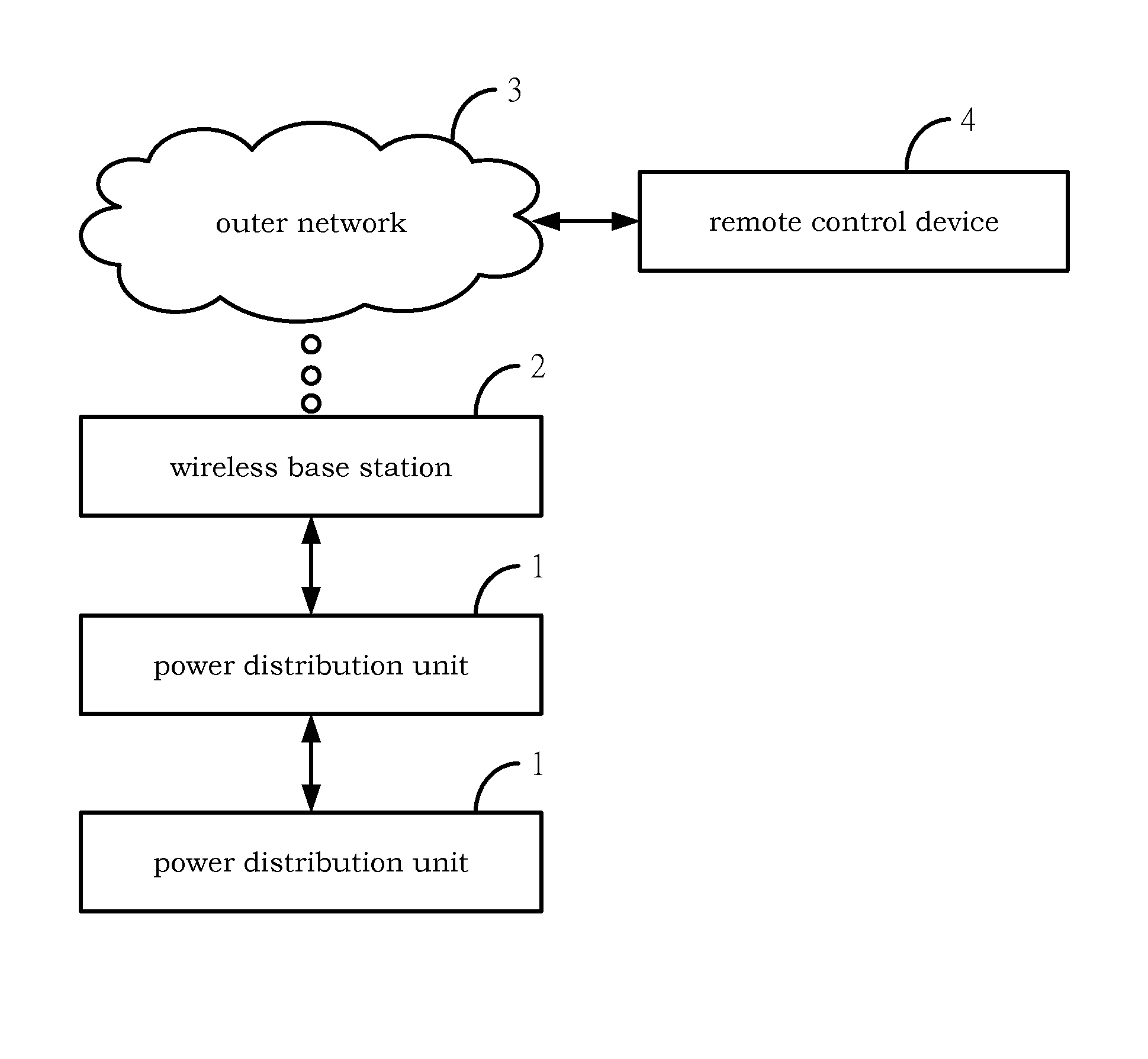
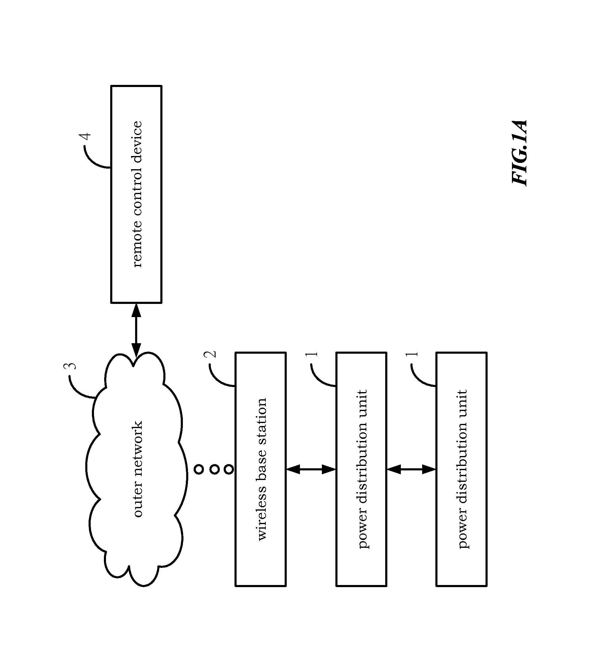
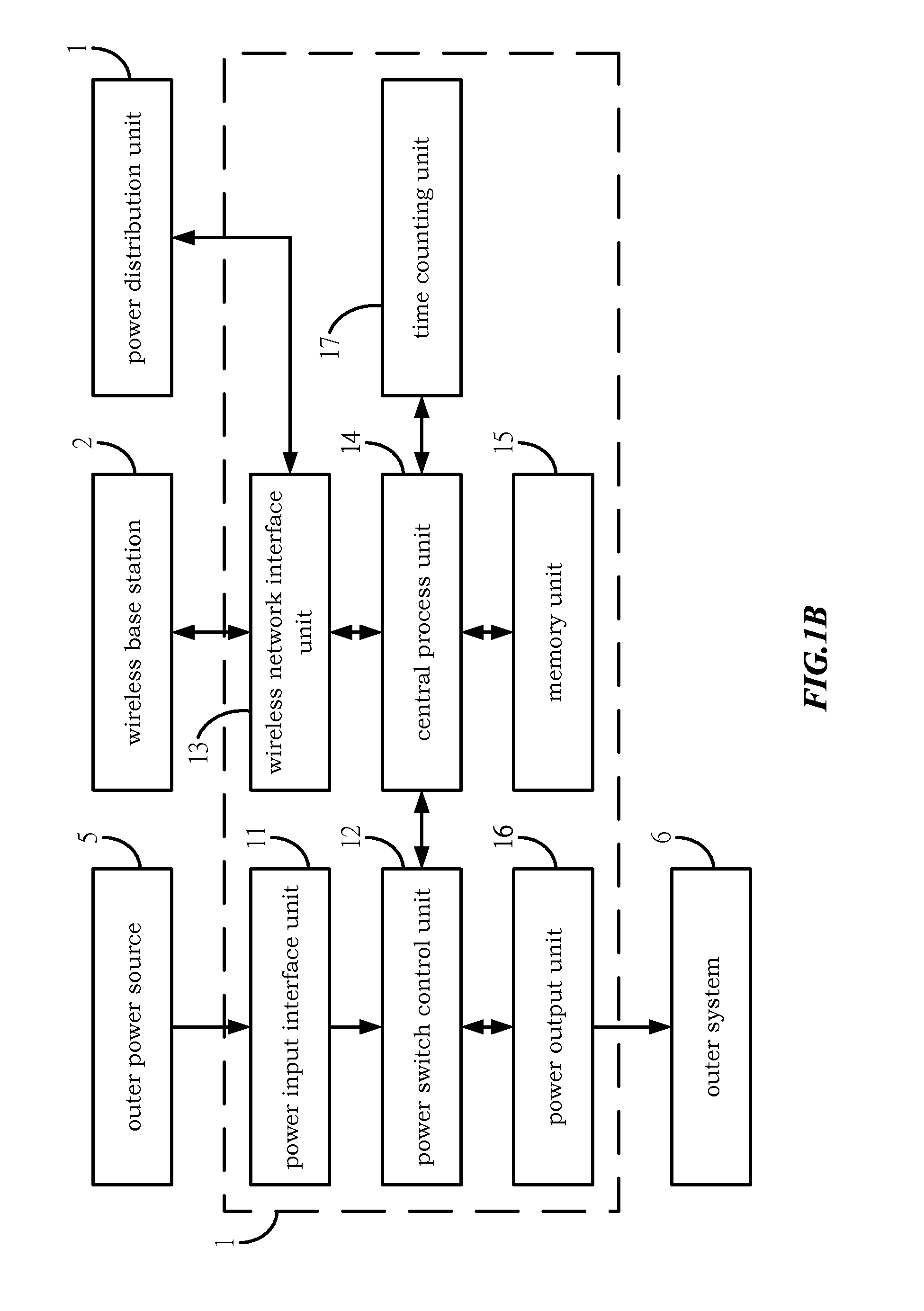
[0033]Please refer to FIG. 1A, FIG. 1B and FIG. 1C, which illustrate a schematic outer structural view of the power outlet control device for a wireless network topology and a distribution method of the present invention, a schematic whole structural view of the power outlet control device for the wireless network topology and the distribution method of the present invention, and a schematic structural view of a central process unit of the power outlet control device for the wireless network topology and the distribution method of the present invention. As shown in figure, the power outlet control device 1 has a power input interface unit 11, a power switch control unit 12, a wireless network interface unit 13, a central process unit 14, a memory unit 15, and a power output unit 16. The power input interface unit 11 connects with an outer power source 5. The power switch ...


PUM


Abstract

A power outlet control device for a wireless network topology has a power input interface unit, a power switch control unit, a wireless network interface unit, a central process unit, a memory unit, and a power output unit. The power input interface unit connects with an outer power source. The power switch control unit distributes and controls the power from the input interface unit. The power output unit further outputs power to an outer system and control the power of the outer system.

Description

BACKGROUND OF THE INVENTION[0001]1. Field of the Invention[0002]The present invention generally relates to a power distribution unit for a wireless network topology and a distribution method thereof, more particularly to a power distribution unit (PDU) that enhances operations and convenience at home and provides a mechanism that lets multiple PDUs be connected with each other through an existing wireless network technology, but still keep the operational convenience.[0003]2. Description of the Prior Art[0004]Internet development by leaps and bounds, a wireless network can be described as the mainstream of the network around the world. No matter academia or industry, they have invested a lot of manpower to research in the fields. The market size of the wireless network is expanding at breakneck speed. Hence, how to develop more innovative and exclusive products for compatibility and functionality is superb, in order to compete in the fierce market place, attaches great importance to...

Claims


Application Information

Patent Timeline
IPC IPC(8): H04W48/16G05F1/66
CPCG05F1/66H04W48/16H04W24/02H04W84/12
Inventor LAI, LI-CHUN
Owner LAI LI CHUN
Why Eureka
Try Eureka