X-ray imaging guiding system for positioning a patient

a guiding system and guiding technology, applied in the direction of patient positioning for diagnostics, instruments, applications, etc., can solve the problems of time-consuming and difficult positioning of technicians, and achieve the effect of facilitating patient positioning and high throughpu

Active Publication Date: 2014-11-27
KONINKLJIJKE PHILIPS NV
View PDF4 Cites 29 Cited by
  • Summary
  • Abstract
  • Description
  • Claims
  • Application Information

AI Technical Summary

Benefits of technology

[0023]For example, an OLED arrangement, being an active display, also provides an active light source that can be integrated into the examination-room's lighting concept. The OLED arrangement can, for example, enhance contrast and thus improve the patient's visual situation.
[0035]According to an aspect of the present invention, information for the exact positioning is provided in a straight forward manner, i.e. as a type of information that is directly understandable by the technician or staff member as well as by the patient himself. This information is provided in form of an image of the anatomy which gives the user an unambiguous impression for the correct position. In other words, intuitive information for the positioning is provided, for example in the exact location of the target position. Thus, instead of analyzing the position of a light cross indicating the central point of an X-ray beam, and to bring that central point in relation to a region of interest, the user, i.e. the patient or the technician, can simply align the anatomy of the patient with the image provided. The positioning information can be provided either as a projection onto the detector surface, or, in case the patient is already arranged in front of the detector surface, as a projection onto the patient's surface. The positioning information can also be provided directly on the detector surface, i.e. on the visible surface of the detector housing or other visible surfaces, for example by an e-paper coating. Since the positioning information is provided in a manner which does not affect the X-ray image acquisition itself, the positioning information can be provided throughout the image acquisition procedure. Thus, a technician can control the correct positioning even when being located in the control room by a visual feedback through a window usually provided between the two rooms. Of course, also a camera can be installed for providing the respective view from one room to the next room, where it is displayed on a monitor. The positioning information being available throughout the image acquisition thus improves the correct positioning and thus helps in avoiding unnecessary image acquisitions.
[0037]According to a further aspect of the present invention, the patient positioning is facilitated such that the target anatomy is placed in front of a measurement chamber, and collimated as tightly as possible, to achieve comparable diagnostic quality, especially for follow-up studies. Besides facilitating the positioning for technicians, it is also possible to use the target positioning information such that the patients themselves or their relatives can carry out the positioning, for example in emerging markets. Thus, for certain examination type, patients can be lined up and radiographed with a very high throughput.

Problems solved by technology

However, it has been shown that patient positioning can be challenging for technicians and requires time, and also staff members, which have to move between the location of the X-ray imaging system, and the location where the control interface for the X-ray imaging system is located, usually a separate room having only visual contact to the patient.

Method used


Image

  • X-ray imaging guiding system for positioning a patient
  • X-ray imaging guiding system for positioning a patient
  • X-ray imaging guiding system for positioning a patient

Examples


Embodiment Construction

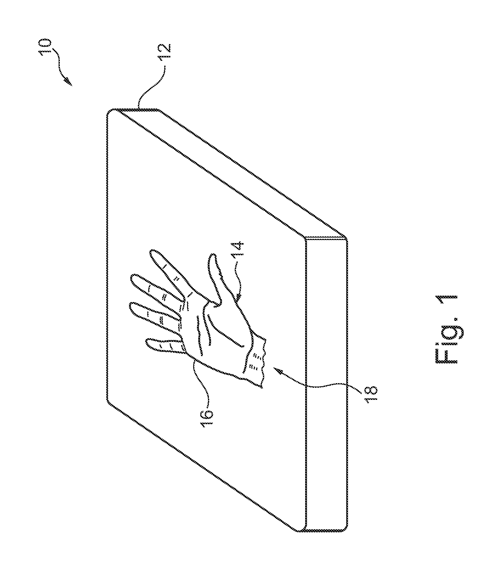
[0057]FIG. 1 shows an X-ray imaging guiding system10 for positioning a patient for X-ray image acquisitions. The X-ray imaging guiding system 10 comprises an X-ray detector arrangement 12 and adaptable graphical positioning information 14.

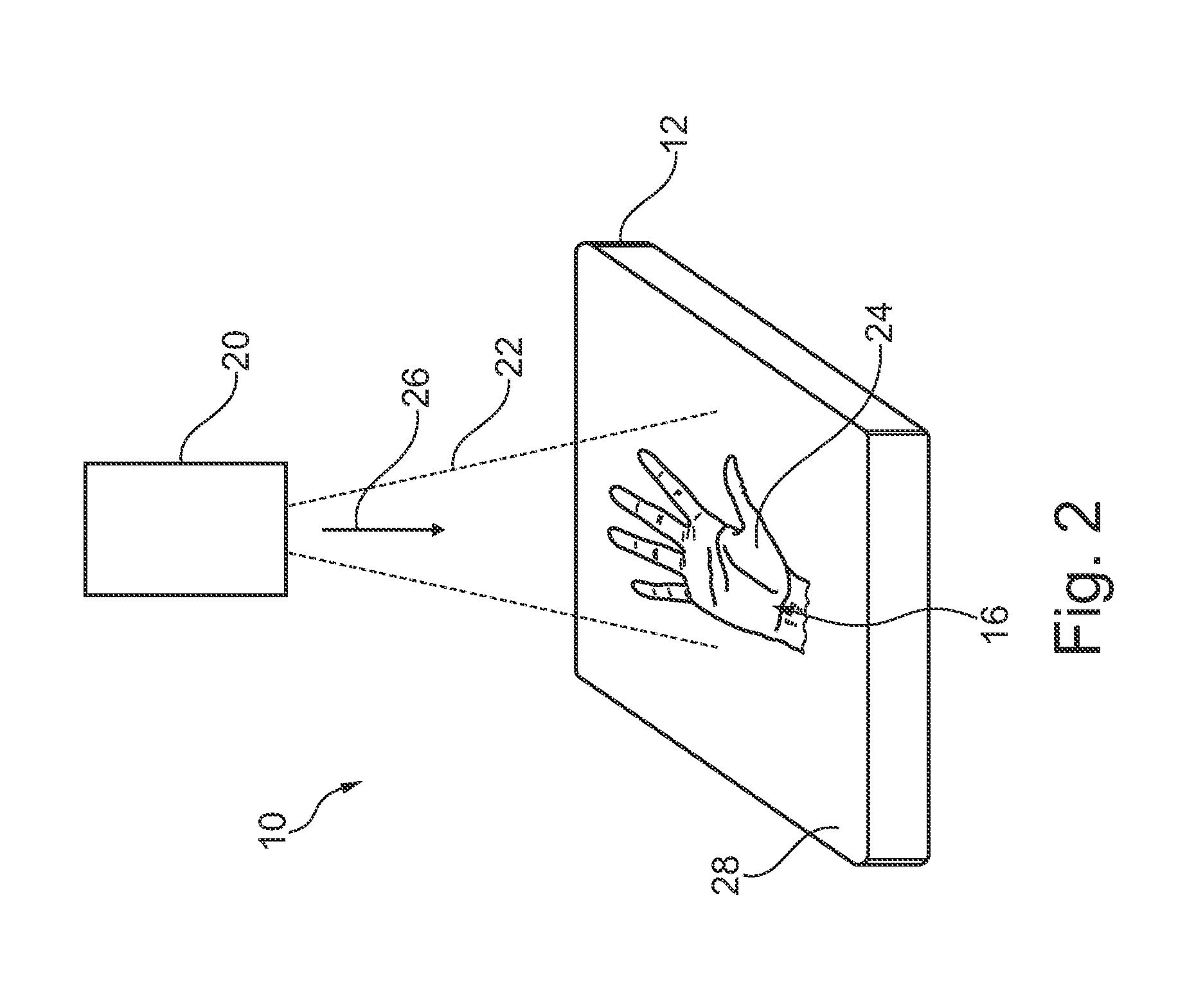
[0058]The graphical positioning information comprises at least a graphical target anatomy representation 16. As an example only, outlines of a human hand are shown as graphical target anatomy representation 16. The graphical target positioning information is provided in spatial relation with the X-ray detector arrangement 12. The graphical target anatomy representation 16 indicates a target position 18 of a respective anatomy of the patient for a determined X-ray image acquisition. The graphical positioning information 14 is adaptable in accordance with the determined X-ray image acquisition.

[0059]As already indicated above, the graphical target anatomy representation 16 can be based on a stored model, which model is adapted to the determined X-ray...


PUM


Abstract

The present invention relates to guiding in positioning a region of interest of a patient for X-ray image acquisition. In order to improve and facilitate positioning of a patient for X-ray image acquisitions, an X-ray imaging guiding system (10) for positioning a patient for X-ray image acquisitions is provided, comprising an X-ray detector arrangement (12), and adaptable graphical positioning information (14). The graphical positioning information comprises at least a graphical target anatomy representation (16). The graphical target positioning information is provided in spatial relation with the X-ray detector arrangement. The graphical target anatomy representation indicates a target position (18) of a respective anatomy of the patient for a determined X-ray image acquisition. Further, the graphical positioning information is adaptable in accordance with the determined X-ray image acquisition.

Description

FIELD OF THE INVENTION[0001]The present invention relates to an X-ray imaging guiding system for positioning a patient for X-ray image acquisitions, an X-ray imaging system, a method for guiding in positioning a region of interest of a patient for X-ray image acquisition, as well as to a computer program element and a computer readable medium.BACKGROUND OF THE INVENTION[0002]In X-ray imaging, patient positioning is a necessity, for example, for minimum dose requirements. A region of interest of a patient, for example a certain organ or a certain region of an extremity, such as a foot or a hand, is placed and thus positioned by a technician. The region of interest is arranged such that the X-radiation will cover a region of interest as much as possible on the one hand, and while avoiding to expose the patient to unnecessary radiation on the other hand, i.e. radiation which radiates through regions that do not belong to the region of interest. Therefore, a light projection, for exampl...

Claims


Application Information

Patent Timeline
Patent Type & Authority Applications(United States)
IPC IPC(8): A61B6/00A61B6/04
CPCA61B6/04A61B6/589A61B6/08A61B6/0492A61B6/06A61B6/4208A61B6/46A61B6/467A61B6/542A61B6/582G01T1/20
Inventor GOOSSEN, ANDRÉLEVRIER, CLAIREVOGTMEIER, GEREONFLORENT, RAOULROOSE, LIESBET HILDE HADEWIJCHVON BERG, JENS
Owner KONINKLJIJKE PHILIPS NV
Why Eureka
Try Eureka