Heat exchange matrix

a technology of heat exchange matrix and heat exchange plate, which is applied in the field of heat exchange plate, can solve the problems of air becoming relatively dry, prone to voluminous, respiratory problems, etc., and achieve the effect of improving stability

Active Publication Date: 2014-12-04
OXYCOM BEHEER BV
View PDF6 Cites 9 Cited by
  • Summary
  • Abstract
  • Description
  • Claims
  • Application Information

AI Technical Summary

Benefits of technology

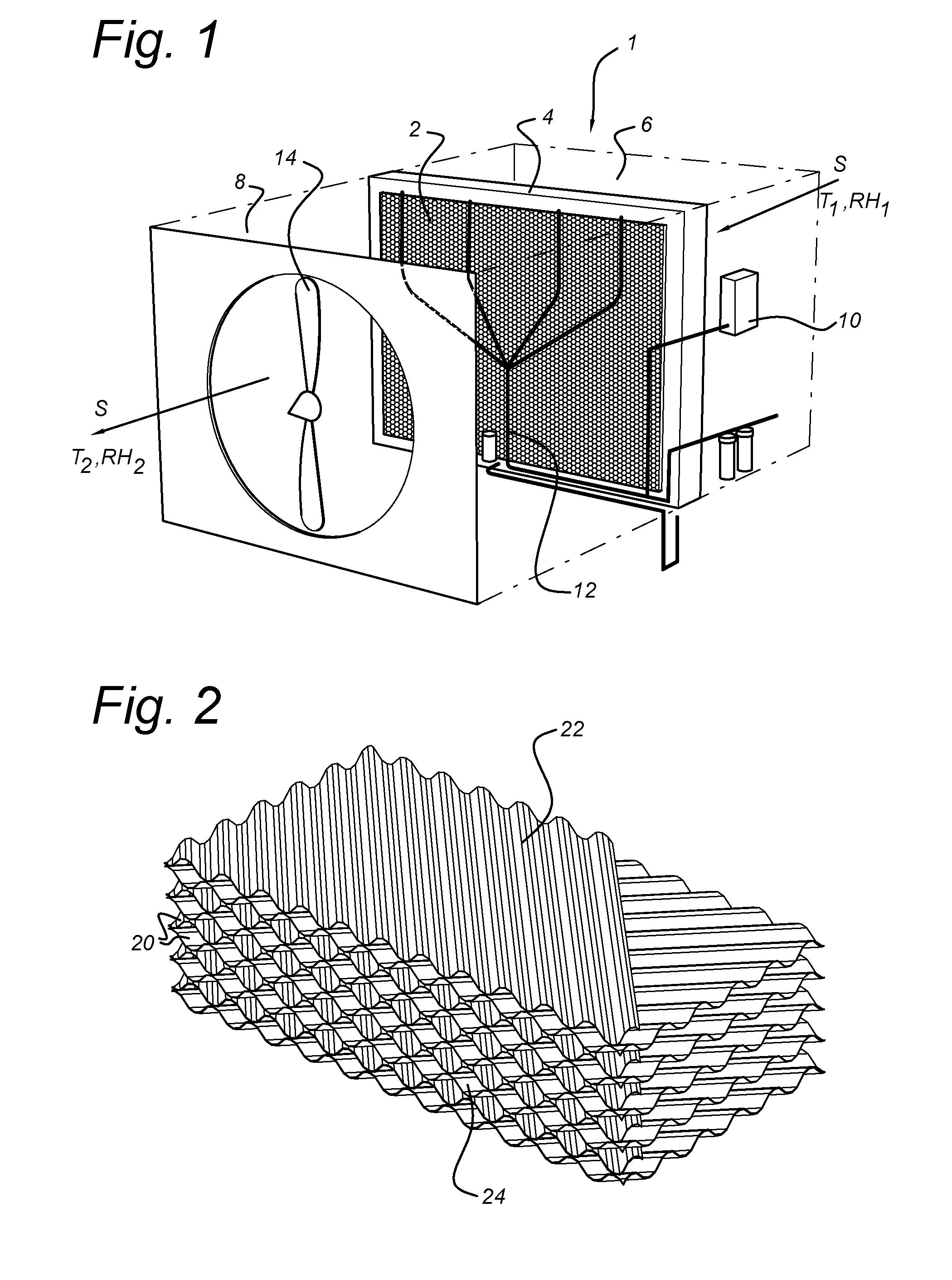
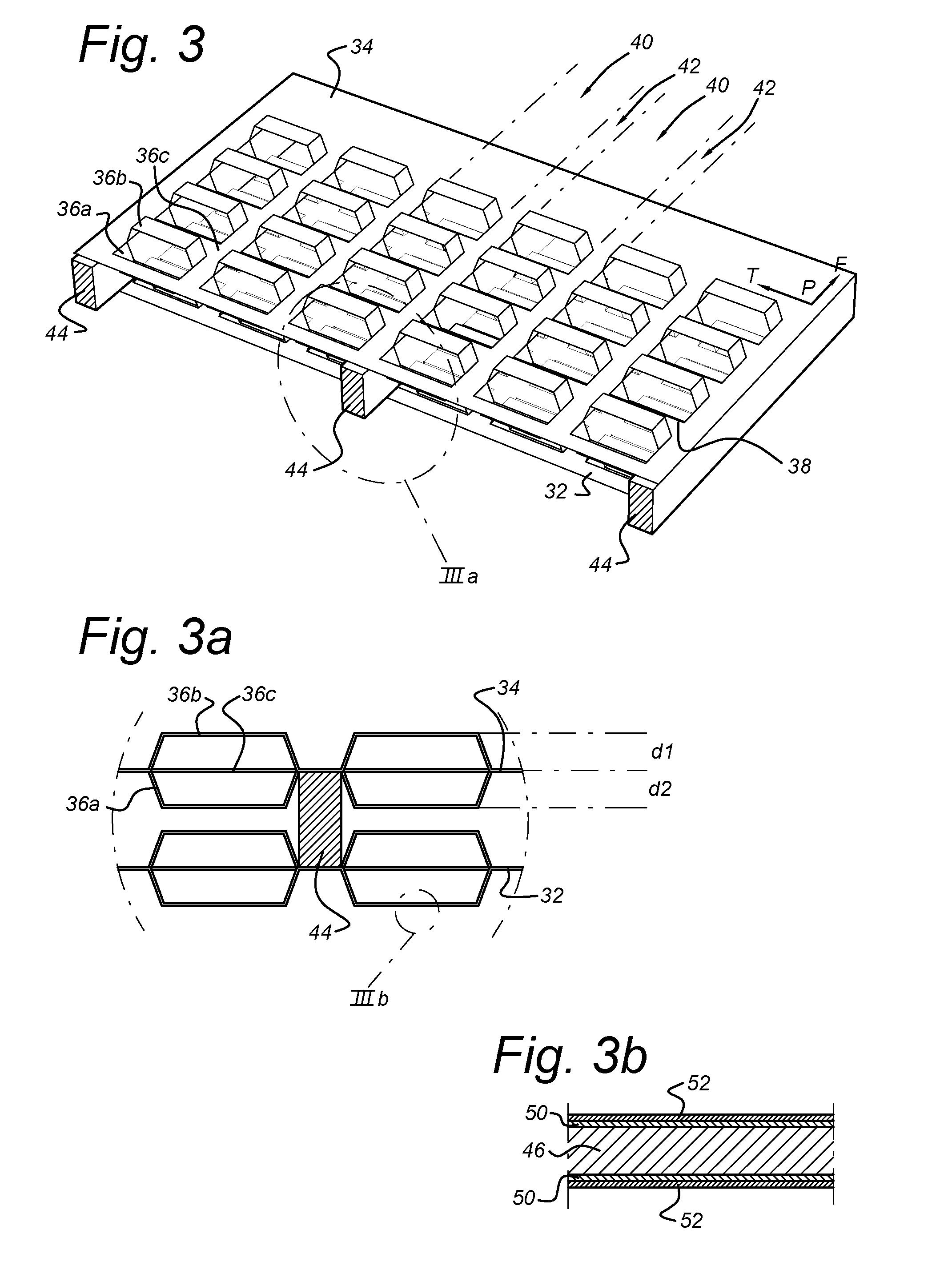
[0013]Although various configurations and orientations of the strips may be considered, nevertheless, in general the strips will lie generally parallel to the flow direction. Without wishing to be bound by theory, it is believed that a disposition of all or most of the strips to lie in the direction of the flow is advantageous in reducing the pressure drop across the heat exchanger.
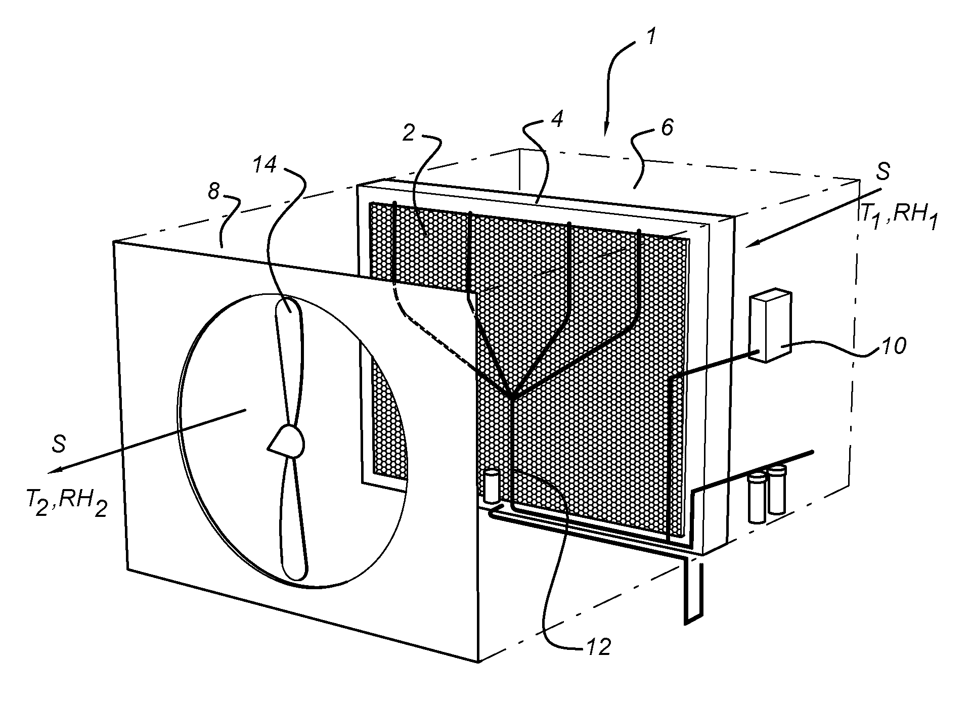
[0036]According to a still further aspect of the invention, an evaporative cooler, adiabatic cooler or humidification unit may comprise such a heat exchange matrix as described above, retained in a housing having at least an air inlet, an air outlet and a fan arrangement for directing air through the matrix in the flow direction. Additionally there may be provided a source of water for wetting the matrix. The device may also be used for air washing or otherwise removing odours, dust and other undesirable substances from a flow of air. In a preferred form, embodied as an adiabatic cooler comprising a source of water for wetting the matrix, the strips extend generally vertically and the flow channel extends generally horizontally, the source of water being arranged to supply water to an upper side of the plurality of foils such that the water can flow downwards along the strips. Such a configuration allows optimal distribution of the water down and through the matrix. In particular, in this configuration, spacers provided to maintain a distance between adjacent foils should not extend in the flow direction as this would impede the downward flow of water. Preferably, spacing is provided by small spots or blobs of adhesive or suitable polymer between adjacent foils. The spots may have a maximum dimension of around 1 cm.

Problems solved by technology

A major problem with prior art devices is that in order to optimise efficiency they tend to become relatively voluminous.
In particular during the winter months, heating systems tend to cause the air to become relatively dry.
This may lead to respiratory problems, static electricity and other discomforts.
Nevertheless, one particular disadvantage of such wheels is their overall bulk.
This is generally related to the volume of material required for effective heat exchange and to the need for an effective flow through area that will not lead to significant pressure drop and an associated high power consumption by the fan.

Method used


Image

  • Heat exchange matrix
  • Heat exchange matrix
  • Heat exchange matrix

Examples


example

[0068]A matrix as described above according to FIG. 4 was constructed and tested. Similar tests were carried out on a conventional matrix material CELDEK™ 5090-15 available from Munters AB. It is noted that the surface area of material per unit volume is comparable for both material. The tests were carried out according to Australian Standard (AS 2913-2000) whereby the supply air has a dry bulb temperature of 38° C. and a wet bulb temperature of 21° C. (21% relative humidity). The saturation efficiency is the actual temperature reduction of the supply air (T in−T out) with respect to the temperature drop that would be required to reach the wet bulb temperature (T wb in).

Saturation efficiency=(T in−T out) / (T in−T wb in).

[0069]The results given in Table 1 below show:[0070]For the same flow rate and the same volume as the example, the comparative material has a 9% lower Wet Bulb Efficiency and an 89% higher pressure drop;[0071]If the length of the comparative material is increased in o...


PUM

PropertyMeasurementUnit
widthaaaaaaaaaa
widthaaaaaaaaaa
widthaaaaaaaaaa

Abstract

A heat exchange matrix includes a plurality of generally planar foils including a water retaining material, arranged in spaced, substantially parallel relationship. Each foil defines a main plane having a flow direction and a transverse direction and the foils include strips that extend a strip length in the transverse direction and are separated from each neighbouring strip in the flow direction and each strip is offset from the main plane by a distance that is different from that of its neighbour. The matrix may be provided in a flow channel for air to be humidified and cooled.

Description

BACKGROUND OF THE INVENTION[0001]1. Field of the Invention[0002]The present invention relates to a heat exchange matrix of the type that can be used as an adiabatic humidifier to introduce moisture to a flow of fluid. The invention further relates to methods of manufacturing such devices. A matrix of this type can operate to provide adiabatic cooling for domestic purposes and may also be used for humidification in combination with conventional air conditioning and heating systems. It may also be used to remove moisture from an airstream in combination with a suitable desiccant.[0003]2. Description of the Related Art[0004]Heat exchange devices of one form or another are present in virtually every device and process. The performance of an action invariably involves the release of energy in the form of heat. If not required, the heat will often be released to ambient via an appropriate heat conducting surface provided e.g. with cooling fins. If the quantity of heat is excessive or if i...

Claims


Application Information

Patent Timeline
Patent Type & Authority Applications(United States)
IPC IPC(8): F28C3/08B23P15/26F24F6/02
CPCF28C3/08B23P15/26F24F6/02B01J19/32B21D53/04F24F3/14F28D19/042F24F2203/10B21D13/00B01J2219/32206B01J2219/3221B01J2219/32251B01J2219/32262B01J2219/32268Y10T29/49359Y02B30/54
Inventor HAKBIJL, MARKREINDERS, JOHANNES ANTONIUS MARIA
Owner OXYCOM BEHEER BV
Why Eureka
Try Eureka