Microparticle detection system

Active Publication Date: 2014-12-04
NGK SPARK PLUG CO LTD
View PDF11 Cites 35 Cited by
  • Summary
  • Abstract
  • Description
  • Claims
  • Application Information

AI Technical Summary

Benefits of technology

[0029]The particulate detection system of claim 1 can detect the amount of particulates by driving the detection section in a state in which the degree of insulation between the first potential member and the second potential member is high. Therefore, the amount of particulates can be detected properly. Also, the system can prevent failure of the drive circuit or the like, which failure would otherwise occur as a result of the drive circuit being driven in a state in which the degree of insulation is low.
[0030]In the particulate detection system of claim 2, when the tested degree of insulation is low, the drive of the detection section by the drive circuit is stopped. By virtue of this, when the degree of insulation is low, in particular, when the degree of insulation is extremely low (a short circuit is formed), it is possible to reliably prevent occurrence of problems such as failure of the drive circuit itself and failure of the detection section, which failures would otherwise occur due to drive of the drive circuit.
[0031]In the particulate detection system of claim 3, a test voltage is applied between the first potential member and the second potential member, and the degree of insulation between the first potential member and the second potential member is tested on the basis of the leak current flowing between the two members or the insulation resistance between the two members.
[0032]Since this method requires application of the test voltage between the first potential member and the second potential member and detection of the current or the resistance, the degree of insulation can be readily tested.
[0033]In the particulate detection system of claim 4, the insulation test means tests the degree of insulation between the first communicating member whic

Problems solved by technology

Therefore, if the filter suffers breakage or a like failure, unpurified

Method used


Image

  • Microparticle detection system
  • Microparticle detection system
  • Microparticle detection system

Examples


Embodiment Construction

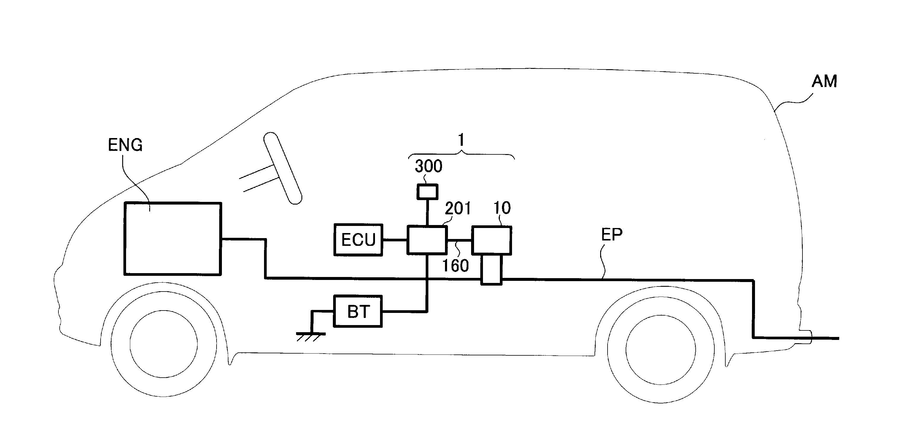
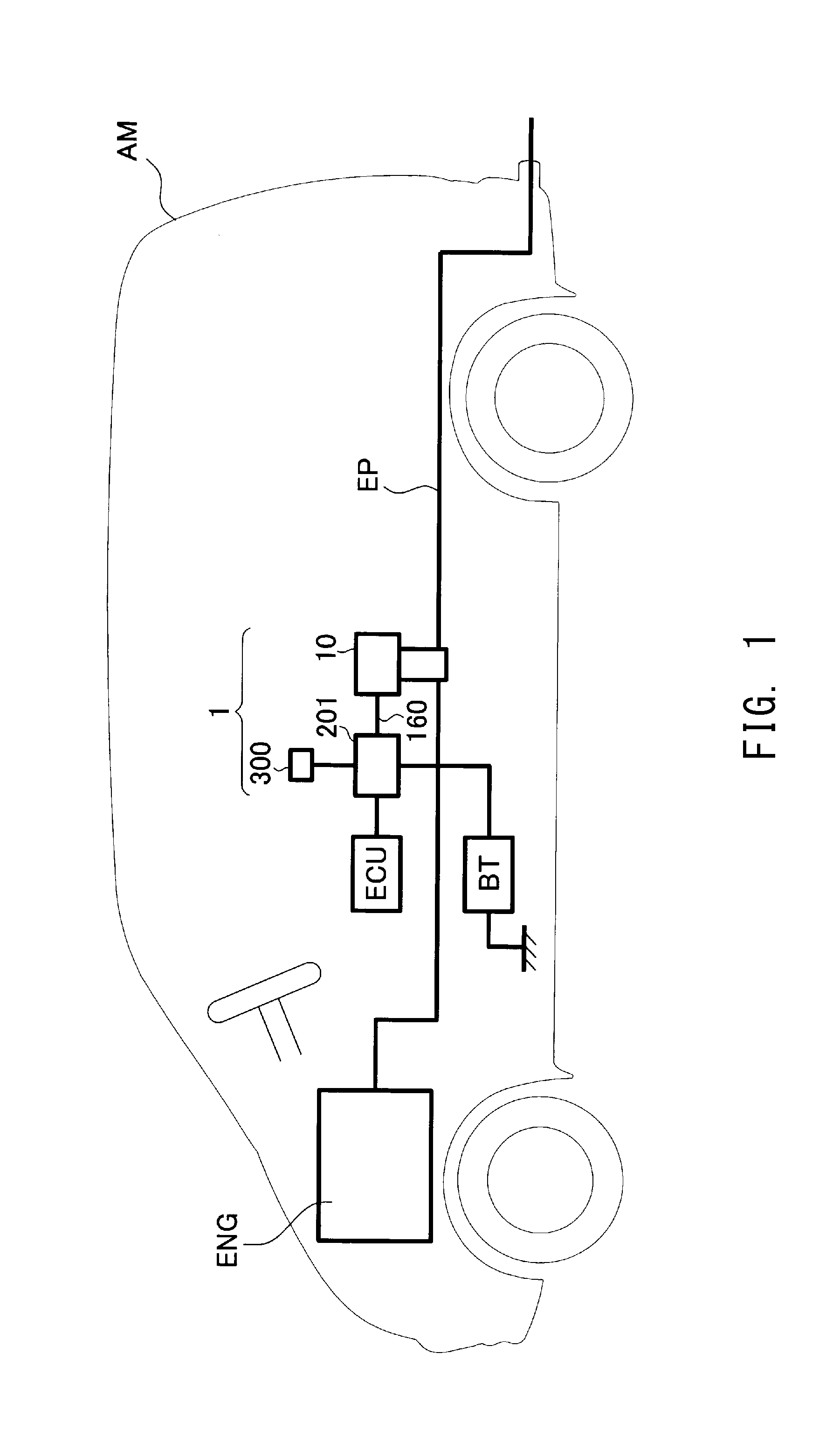
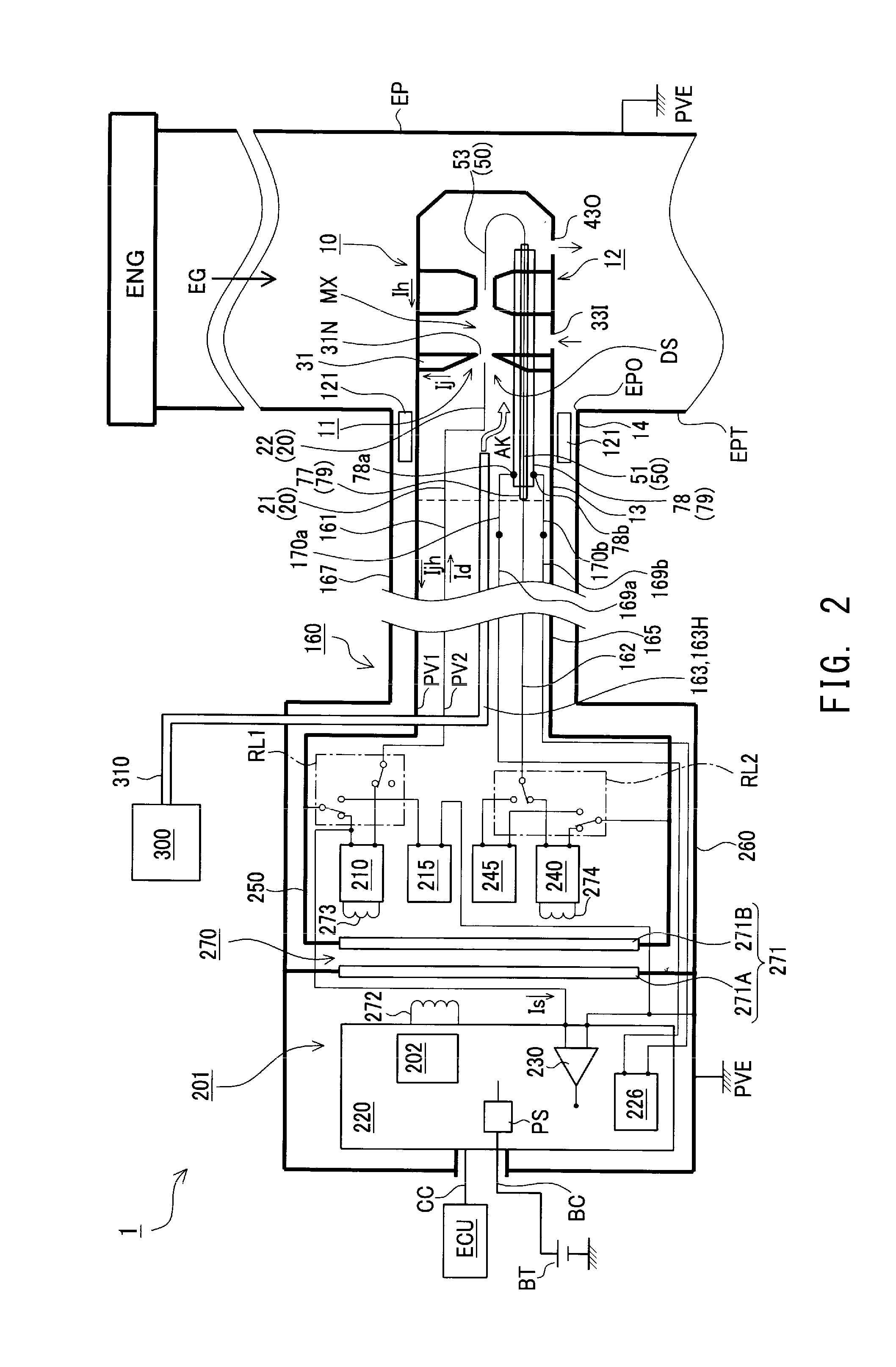
[0053]A particulate detection system 1 according to the present embodiment will be described with reference to the drawings. The particulate detection system 1 of the present embodiment is attached to an exhaust pipe EP of an engine ENG (an internal combustion engine) mounted on a vehicle AM, and detects the amount of particulates S (soot, etc.) contained in the exhaust gas EG flowing through the exhaust pipe EP (see FIG. 1). This system 1 is mainly composed of a detection section 10, a circuit section 201, and a feed pump 300 which is a compressed air source for producing compressed air AK (see FIG. 2).

[0054]The detection section 10 is attached to a mount portion EPT of the exhaust pipe EP (a gas flow pipe) where a mount opening EPO is formed. A portion of the detection section 10 (located on the right side (the distal end side) of the mount portion EPT in FIG. 2) extends into the interior of the exhaust pipe EP through the mount opening EPO and is to come into contact with the exh...


PUM


Abstract

A particulate detection system (1) for detecting the amount of particulates S in a gas under measurement EG includes a detection section (10), a drive circuit (210, 240), and a drive control section (225). The detection section includes a first potential member (31, 12, 13) maintained at a first potential PV1, a second potential member (14, 51, 53) maintained at a second potential PVE, PV3, and an insulating member (121, 77, 76) disposed between the first and second potential members. The system includes insulation test means (215, S3, 245, S5) for testing the degree of insulation between the first and second potential members. The drive control section includes drive permission/prohibition determination means S4, S6 for determining, on the basis of the degree of insulation tested by the insulation test means, whether to permit the drive of the detection section by the drive circuit.

Description

TECHNICAL FIELD[0001]The present invention relates to a particulate (microparticule) detection system for detecting the amount of particulates contained in a gas under measurement which flows through a gas flow pipe.BACKGROUND ART[0002]Measurement of the amount of particulates contained in a gas is demanded in some situations. For example, exhaust gas discharged from an internal combustion engine (for example, a diesel engine or a gasoline engine) may contain particulates such as soot.[0003]Exhaust gas containing such particulates is purified by means of collecting the particulates through use of a filter. Therefore, if the filter suffers breakage or a like failure, unpurified exhaust gas is discharged directly to the downstream side of the filter.[0004]Therefore, there has been demanded a particulate detection system which can detect the amount of particulates contained in exhaust gas on the downstream side of the filter in order to directly measure the amount of particulates conta...

Claims


Application Information

Patent Timeline
IPC IPC(8): F01N11/00G01N27/68G01M15/10
CPCF01N11/00G01N27/68G01M15/102F01N2560/05G01N15/0656G01N2015/0046G01R31/52
Inventor MOTOMURA, MASAYUKISUGIYAMA, TAKESHITASHIMA, KEISUKEMATSUOKA, TOSHIYAYOKOI, HITOSHI
Owner NGK SPARK PLUG CO LTD
Why Eureka
Try Eureka