
Canister

a canister and canister technology, applied in the field of canisters, can solve the problems of insufficient use of adsorbent, inconvenient use of adsorbent, and drawbacks of conventional canisters, so as to prevent a leakage of fuel components and improve the adsorption ability of canisters.

Inactive Publication Date: 2014-12-04
MAHLE FILTER SYST JAPAN CORP
View PDF9 Cites 5 Cited by
  • Summary
  • Abstract
  • Description
  • Claims
  • Application Information

AI Technical Summary

Benefits of technology

The present invention provides an improved canister that can overcome drawbacks in conventional canisters. The canister has a charge port located at the eccentric section, which leads to non-uniform distribution of adsorption quantity in a circumferential direction in each cross-section. However, the invention improves the adsorption ability of the canister and prevents leakage of fuel components due to insufficient purging. The invention achieves this by delivering a gas flow in a radial direction all over the circumference, making full use of the entire adsorbing material and eliminating bias in the gas flow.

Problems solved by technology

However, drawbacks have been encountered in conventional canisters.
However, charging is to progress more easily at locations closer to the charge port regardless of the presence of the slight clearance provided by the porous plate since the charge port is disposed at the eccentric section, which brings about a nonuniformity of the distribution of adsorption quantity in a circumferential direction in each cross-section.
After all, the adsorbent is not fully used in its entirety even if purging can progress uniformly.

Method used


Image

  • Canister
  • Canister
  • Canister

Examples


Embodiment Construction

[0024]Referring now to the accompanying drawings, an embodiment of the present invention will specifically be discussed.

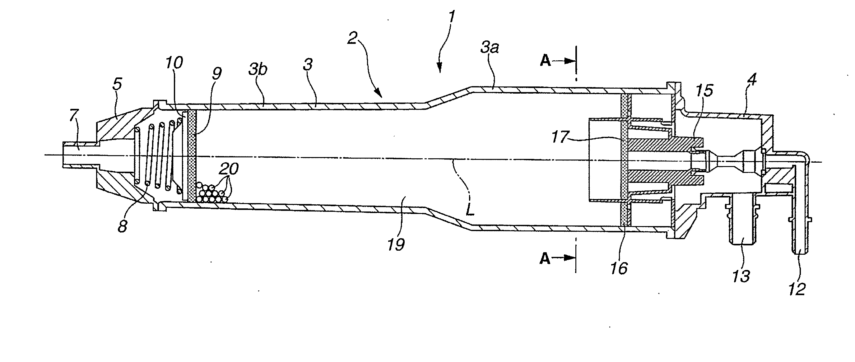
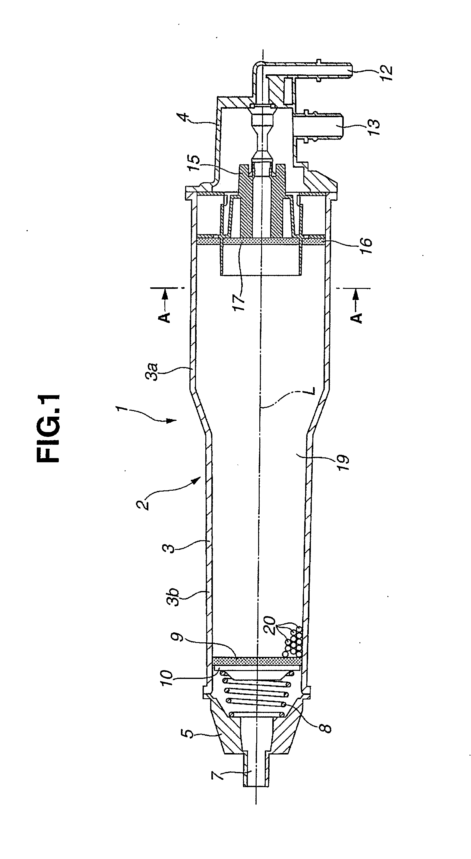
[0025]FIG. 1 is a longitudinal sectional view of an embodiment of a canister 1 according to the present invention. The canister 1 is provided to have a plastic casing 2. The casing 2 is comprised mainly of: a cylindrical main body 3 (a perfect circle in cross section) having a large-diameter part 3a and a small-diameter part 3b and having as its both ends a large-diameter part 3a side open end part and a small-diameter part 3b side open end part; a charge / purge side end cover 4 attached to the large-diameter part 3a side open end part of the main body 3; and a drain side end cover 5 attached to the small-diameter part 3b side open end part of the main body 3.

[0026]The drain side end cover 5 is formed having at its center a drain port 7 that extends along a center axis L of the main body 3. Additionally, the drain side end cover 5 holds a screen member 9 and a latti...


PUM


Abstract

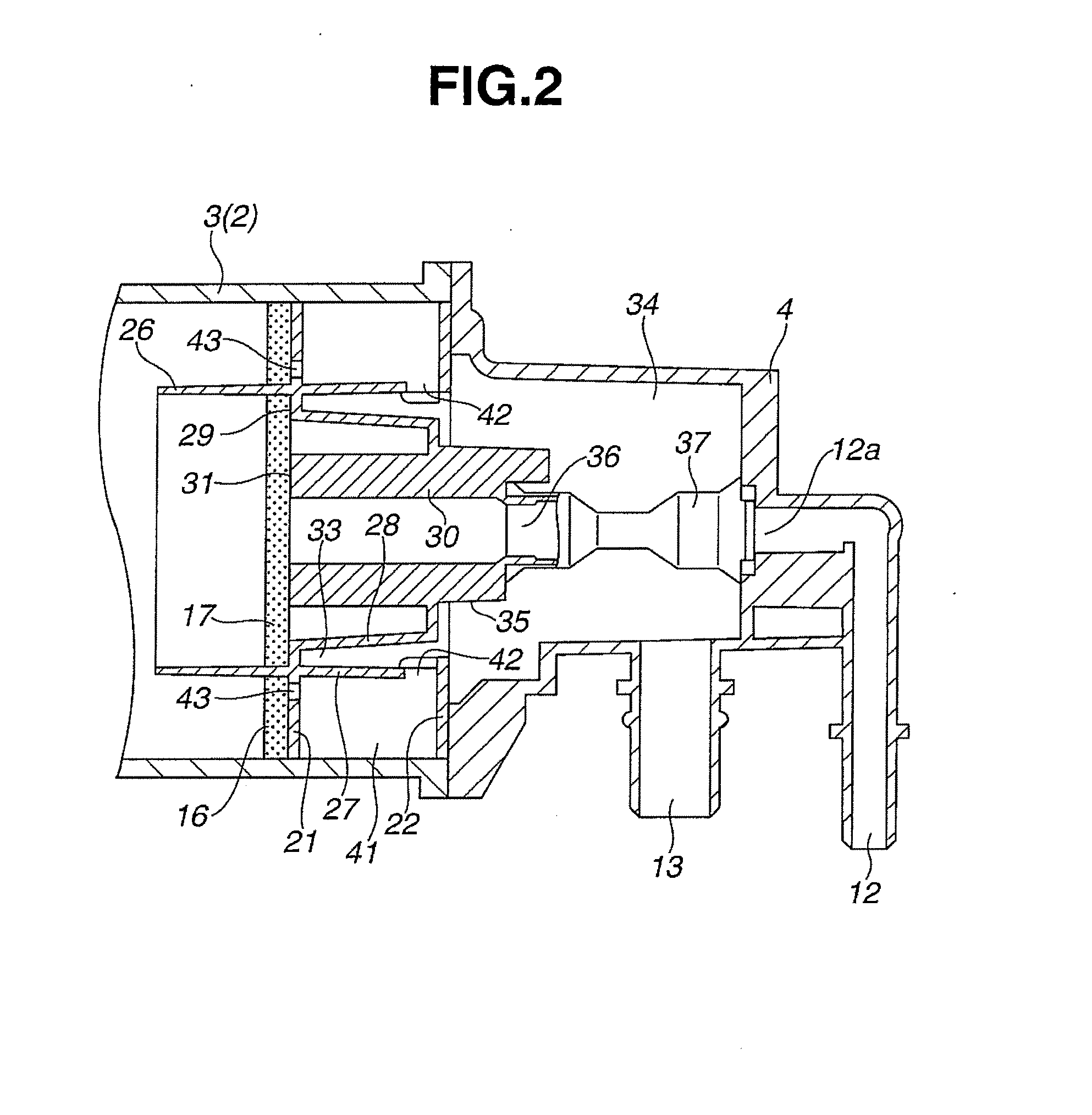
A canister includes: a casing charged with an adsorbing material; a charge port and a purge port disposed at one end of the casing; a drain port disposed at the other end of the casing; a flange section for defining an outer peripheral part of one end of an adsorbent chamber; a first cylindrical section projected from the flange section toward the adsorbent chamber and concentric with the casing; and a second cylindrical section extending from the flange section in the opposite direction and concentric with the casing. A space defined inside the first cylindrical section is provided to communicate with one of the charge port and the purge port, while a diffusion chamber communicates with the other of the charge port and the purge port. The flange section has orifices located adjacent to the first cylindrical section thereby communicating the adsorbent chamber and the diffusion chamber with each other.

Description

BACKGROUND OF THE INVENTION[0001]This invention relates to improvements in a canister used in a vaporized fuel processing system for an automotive vehicle, and more particularly to a canister provided to have a cylindrically shaped casing in which longitudinal direction a gas is to flow.[0002]As is well known, in an automotive vehicle using an engine, a vaporized fuel processing system having a canister as a main body is equipped in order to suppress a discharge of vaporized fuel within a fuel tank to the atmosphere.[0003]The canister is filled with an adsorbent such as an activated carbon or so forth within a casing. While vaporized fuel generated within the fuel tank at a time of a vehicle stop is adsorbed onto the adsorbent, a fuel component is desorbed from the adsorbent by means of the atmosphere introduced through a drain port (also referred to as an atmosphere port) at a time of an engine operation and then sucked into an intake air system of the engine.[0004]In the canister,...

Claims


Application Information

Patent Timeline
Patent Type & Authority Applications(United States)
IPC IPC(8): F02M25/08
CPCF02M25/0872F02M25/0854
Inventor OMICHI, JUNPEIARASE, YUJIHASUMI, TAKASHI
Owner MAHLE FILTER SYST JAPAN CORP
Learn More