
Motor controller

Active Publication Date: 2014-12-04
NIDEC CORP
View PDF0 Cites 6 Cited by
  • Summary
  • Abstract
  • Description
  • Claims
  • Application Information

AI Technical Summary

Benefits of technology

The present invention provides a motor controller for a switched reluctance motor that simplifies the process of controlling the motor. The motor controller includes an inverter, a torque and flux estimator, a switching pattern selector, and a reference flux calculator. The torque and flux estimator uses the output from the inverter and the rotor angle to estimate the torque and flux generated in the switched reluctance motor. The switching pattern selector selects one of multiple switching patterns based on the estimated torque and flux, and the reference flux calculator obtains the reference flux from a flux trajectory and the rotor angle based on the reference torque and the rotating speed of the switched reluctance motor. This simplifies the control of the switched reluctance motor.

Problems solved by technology

Using discrete components in an inverter instead of a single module increases cost, weight, size, assembling time, and complexity, and reduces reliability and ruggedness of the inverter.
Further, because these inverters must have special topologies, they cannot be used for any other type of motors.
Furthermore, inverters for an SRM need individual algorithms for high, middle, and low speeds, which increase the complexity of the system and setting time.

Method used


Image

  • Motor controller
  • Motor controller
  • Motor controller

Examples


Embodiment Construction

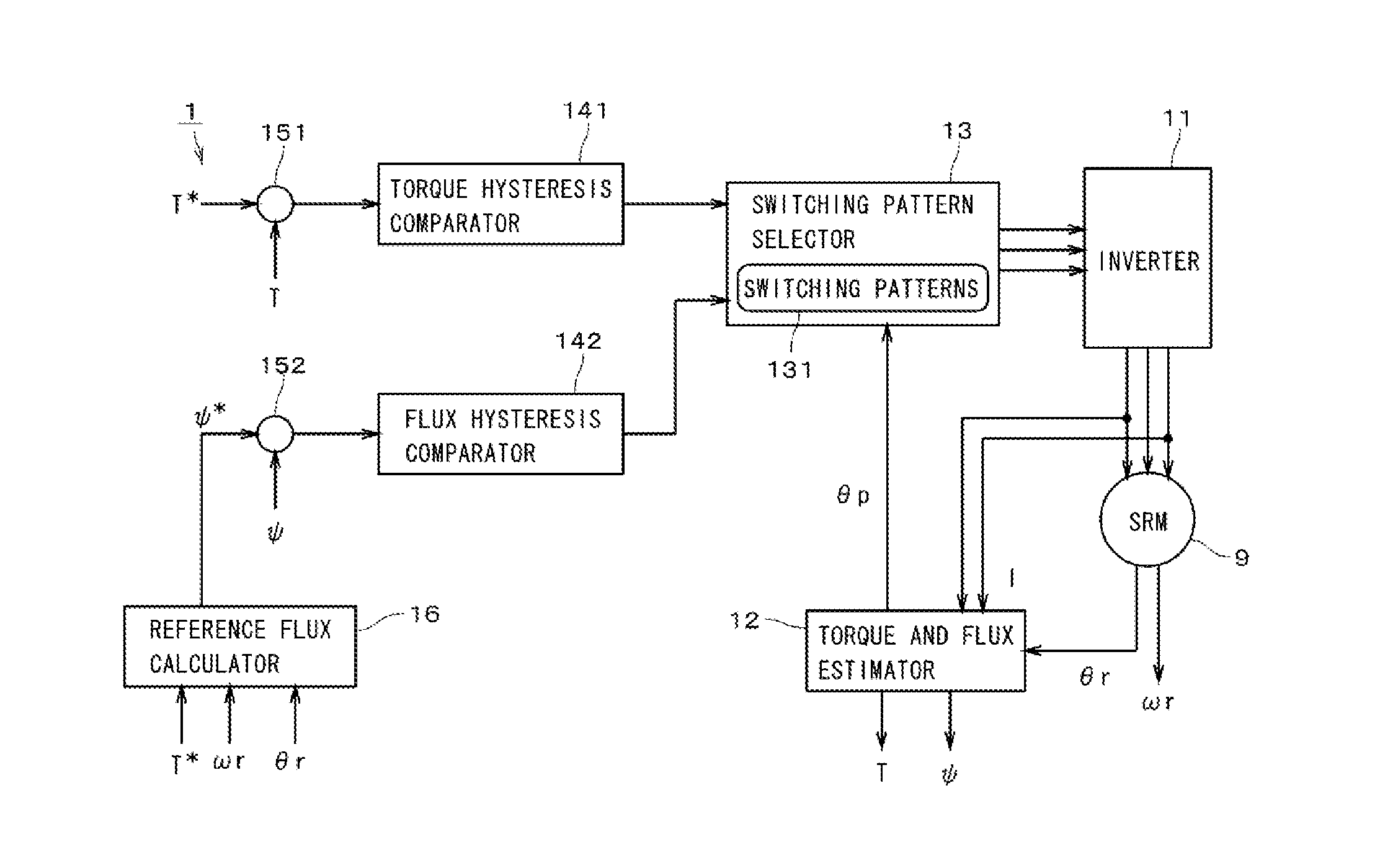
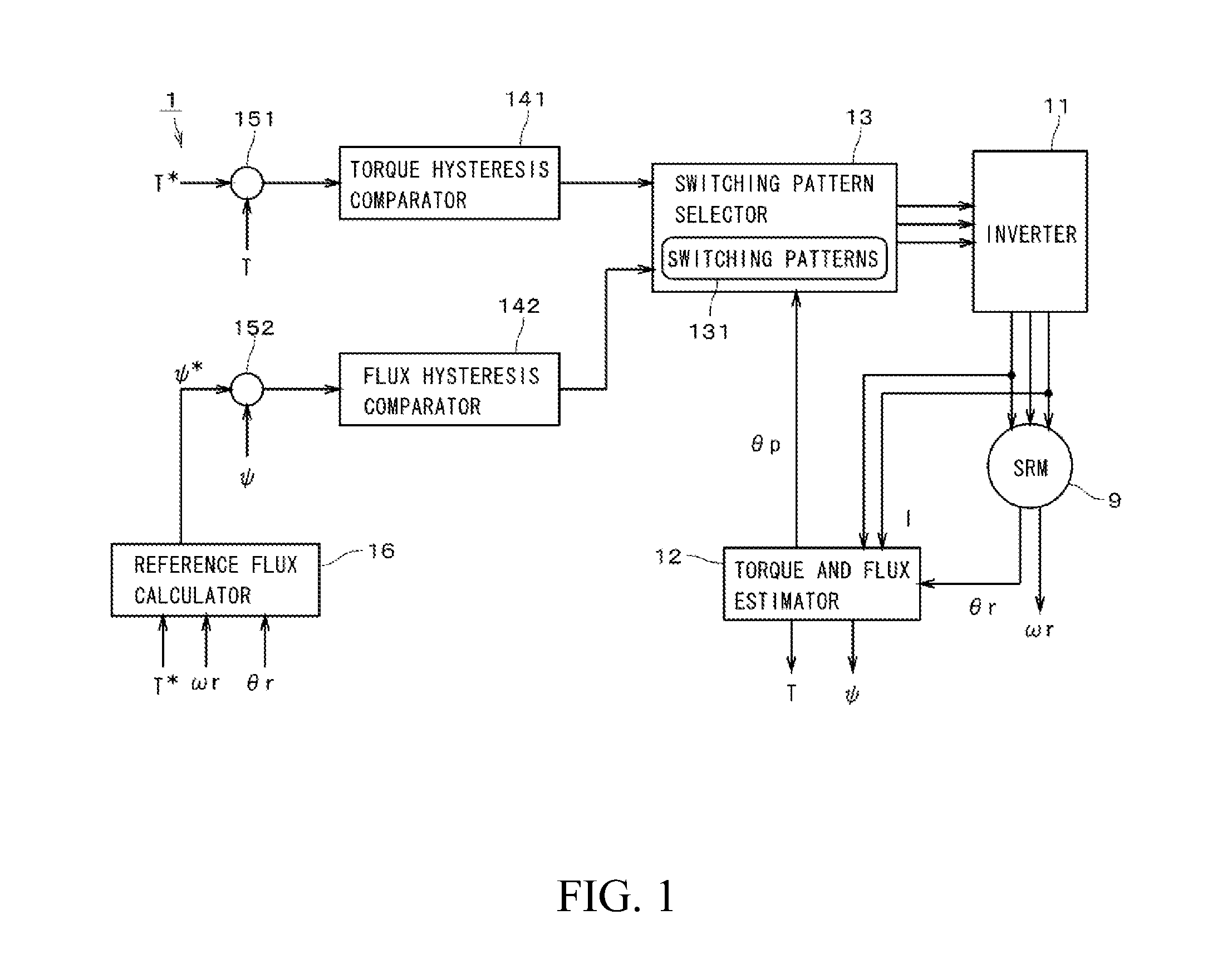
[0027]FIG. 1 is a block diagram showing components of a motor controller 1 according to a preferred embodiment of the present invention. The motor controller 1 is configured to control an SRM (Switched Reluctance Motor) 9 under DTC (Direct Torque Control).

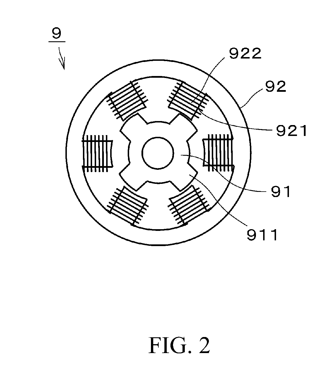
[0028]FIG. 2 is a schematic view of the SRM 9. The SRM 9 includes a rotor 91 and a stator 92. The rotor 91 is rotatably supported around the rotating axis by a bearing mechanism (not shown). The rotor 91 preferably includes a plurality of portions 911 protruding toward the stator 92, and the stator 92 preferably includes a plurality of portions 921 protruding toward the rotor 91, in other words, the SRM 9 preferably has double saliency. The core of the stator 92 is preferably defined by a steel lamination. A wire is preferably wound around each protruding potion 921 of the stator 92 to define a coil 922. The rotor 91 is preferably defined by a steel lamination and does not include either of a coil or a permanent magnet. Torque is p...


PUM


Abstract

A motor controller configured to control an SRM includes an inverter connected to an SRM, a torque and flux estimator configured to estimate a torque and a flux generated in the SRM as an estimated torque and an estimated flux, based on output from the inverter and a rotor angle of the switched reluctance motor, a switching pattern selector configured to select one of a plurality of switching patterns based on comparing a result of a reference torque and the estimated torque, comparing a result of a reference flux and the estimated flux, and a flux phase angle, and performing switching of the inverter in accordance with a selected switching pattern, and a reference flux calculator configured to obtain the reference flux from a flux trajectory and the rotor angle changing the flux trajectory, the flux trajectory indicating a relationship between the rotor angle and the reference flux.

Description

BACKGROUND OF THE INVENTION[0001]1. Field of the Invention[0002]The present invention relates to a motor controller and more specifically to a motor controller configured to control a switched reluctance motor.[0003]2. Description of the Related Art[0004]Switched reluctance motors have been mentioned recently because of their advantage of low manufacturing costs and simple, rugged structure. A switched reluctance motor (hereinafter, referred to as “SRM”) does not have a rotor winding or a permanent-magnet, and has excellent robustness at high speeds and a wide speed range. In an SRM, torque is generated by applying current to stator windings while inductance is changing. If current is applied when the inductance is increasing, positive torque is created, and if current is applied when inductance is decreasing, negative torque is created.[0005]To control the SRM efficiently, individual algorithms are usually used in high, middle, and low speeds. For example, in a low speed, a choppin...

Claims


Application Information

Patent Timeline
IPC IPC(8): H02P25/08
CPCH02P25/085H02P25/08H02P23/30H02P25/092
Inventor AHMAD, GHADERI
Owner NIDEC CORP
Features
  • Generate Ideas
  • Intellectual Property
  • Life Sciences
  • Materials
  • Tech Scout
  • Unparalleled Data Quality
  • Higher Quality Content
  • 60% Fewer Hallucinations
Learn More