
projector

a projector and controller technology, applied in the field of projectors, can solve the problems of insufficient cooling of the second controller and other heated components of the projector, and achieve the effects of reducing wireless communication, stable wireless communication, and efficient cooling of wireless devices

Active Publication Date: 2014-12-04
SEIKO EPSON CORP
View PDF2 Cites 6 Cited by
  • Summary
  • Abstract
  • Description
  • Claims
  • Application Information

AI Technical Summary

Benefits of technology

The patent describes a projector that can improve its appearance and cooling efficiency when attaching a functional device, such as a wireless device for wireless communication. The projector can have a different shape when the functional device is attached, allowing for a cover member that matches the shape of the functional device. This results in a more convenient and improved-looking projector. Additionally, the projector can have an improved exterior appearance by forming a second exhaust port in the cover member that matches the shape of the functional device. This also helps to cool the functional device effectively. The patent also mentions that the position of the transmission device and the receiver or transmitter of the wireless device can be optimized to reduce interference and improve wireless communication reliability.

Problems solved by technology

In this case, however, the second controller blocks the exhaust port, which faces the discharge port, undesirably resulting in insufficient cooling of the second controller and other heated components in the projector.

Method used


Image

  • projector
  • projector
  • projector

Examples


embodiment

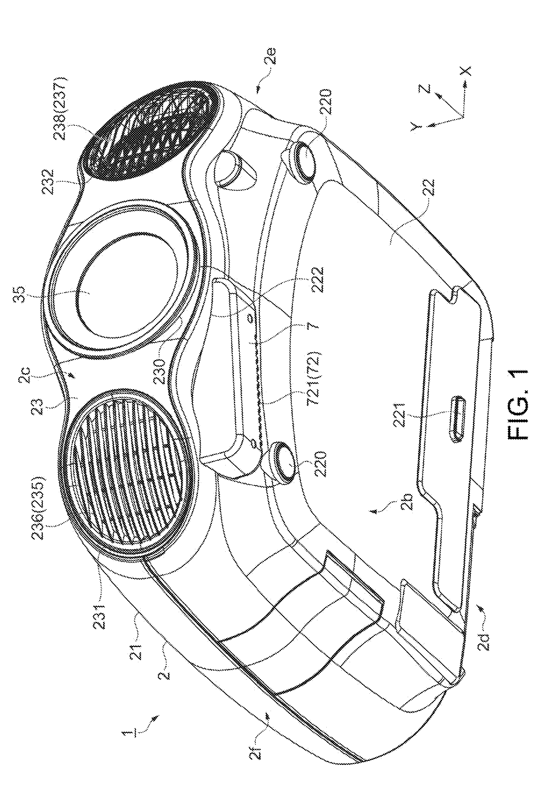
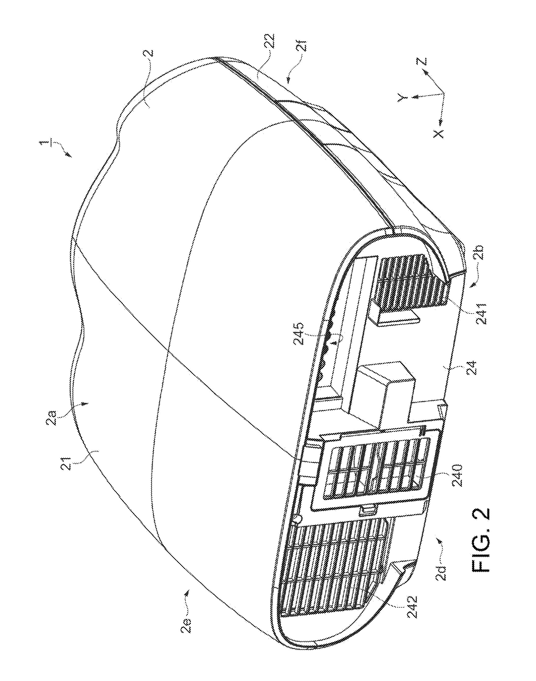
[0034]FIGS. 1 and 2 are exterior perspective views of a projector 1 according to the embodiment. Specifically, FIG. 1 is a perspective view of the projector 1 viewed in an obliquely upward direction from the side where a front surface 2c is present, and FIG. 2 is a perspective view of the projector 1 viewed in an obliquely downward direction from the side where a rear surface 2d is present.

[0035]In the following figures including FIG. 1, an XYZ orthogonal coordinate system is added thereto and used as appropriate for ease of description. In the XYZ orthogonal coordinate system, a Z axis (+Z direction) represents a direction in which image light is projected from the projector 1. An X axis is an axis perpendicular to the Z axis and extending horizontally (rightward and leftward) (+X direction represents rightward direction when front end surface of projection lens 35 is viewed from front), and a Y axis is an axis perpendicular to the Z and X axes and extending vertically (upward and ...


PUM


Abstract

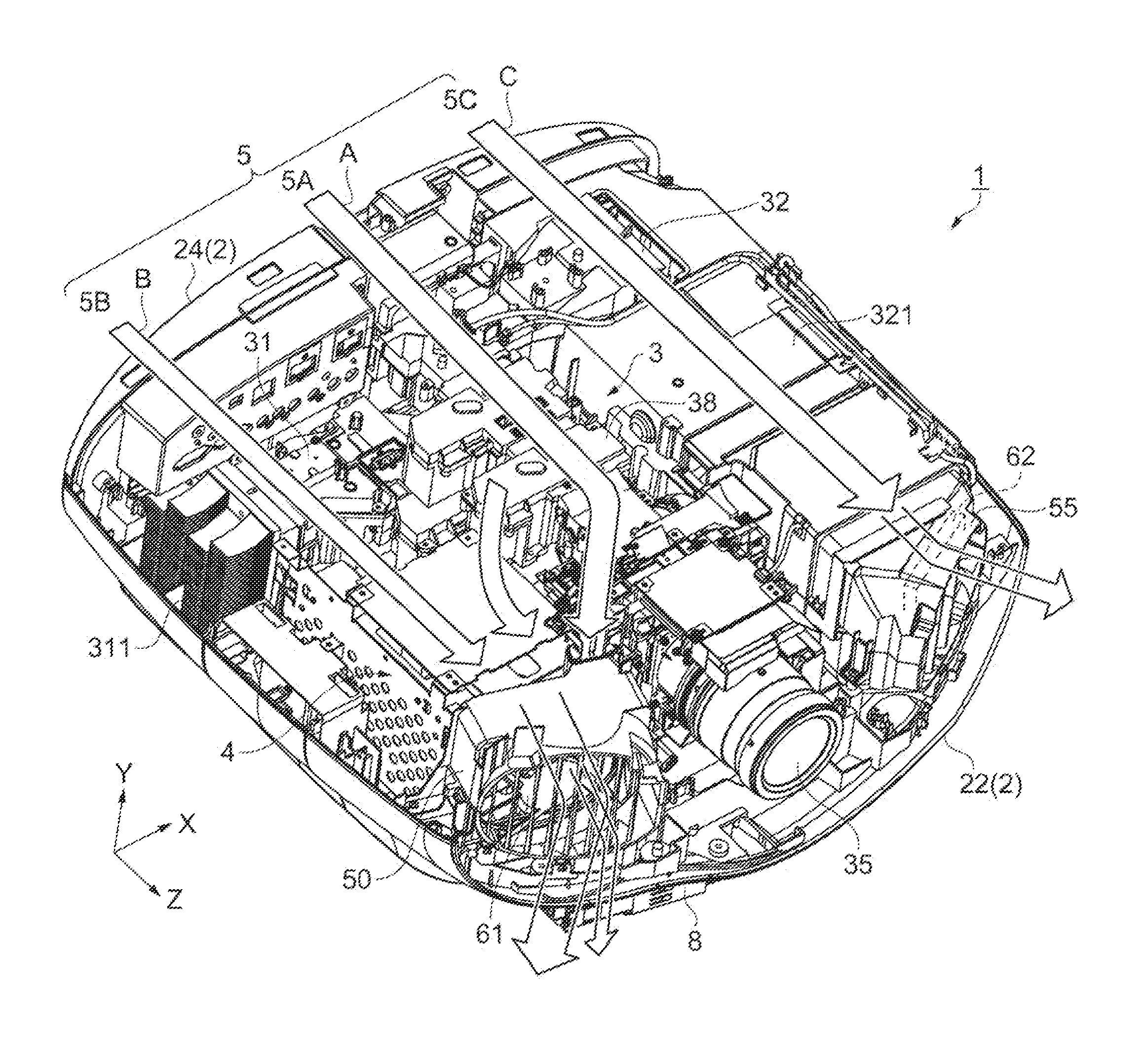
A projector includes a light source apparatus, a light modulator that modulates a light flux outputted from the light source apparatus in accordance with image information, a projection lens that projects the light flux modulated by the light modulator, an exterior enclosure that accommodates the light source apparatus, the light modulator, and the projection lens, an exhaust fan (first exhaust fan) that exhausts air inside the exterior enclosure out thereof through an exhaust port (first light source exhaust port) provided in the exterior enclosure, and a functional device (wireless device) that provides a predetermined function and is heated to a temperature higher than the temperature of the exhaust air from the first exhaust fan. The wireless device is disposed in a position downstream of the first exhaust fan, and part of the exhaust air discharged from the first exhaust fan flows to the wireless device.

Description

BACKGROUND[0001]1. Technical Field[0002]The present invention relates to a projector.[0003]2. Related Art[0004]There is a known projector of related art that modulates a light flux outputted from a light source apparatus in accordance with image information and projects the modulated light flux through a projection lens. A projector of this type includes a cooling mechanism formed, for example, of a cooling fan to reduce the amount of heat generated by a component of the projector due to light emission operation of a light source.[0005]On the other hand, recent advances in wireless transmission technologies lead to a proposed system including a receiver that receives a video signal wirelessly transmitted from an external apparatus (see JP-A-2010-74671, for example).[0006]JP-A-2012-226298 discloses a cooling mechanism including (a) a light modulator, (b) a projection lens, (c) a first controller for driving the light modulator, (d) a second controller for providing a predetermined fu...

Claims


Application Information

Patent Timeline
Patent Type & Authority Applications(United States)
IPC IPC(8): G03B21/16
CPCG03B21/16
Inventor TSUCHITANI, HIROSHIASAMI, KENICHIITO, MASATOSHI
Owner SEIKO EPSON CORP
Learn More