Radio Receiver Having Enhanced Automatic Gain Control Circuitry

Active Publication Date: 2014-12-04
SILICON LAB INC
View PDF7 Cites 4 Cited by
  • Summary
  • Abstract
  • Description
  • Claims
  • Application Information

AI Technical Summary

Benefits of technology

[0002]According to one aspect, an apparatus includes an input terminal to receive a radio frequency (RF) signal and to communicate the RF signal to a low noise amplifier (LNA) via an input signal path, and a capacitor attenuator coupled to the input terminal to attenuate the RF signal by a controllable amount and having a first portio

Problems solved by technology

When an amplitude modulated (AM) radio frequency receiver moves near a source of low frequency noise (such as power line noise, traffic light noise, Integrated Services Digital Network (ISDN) noise, other low frequency noise and their associated harmonics), low frequency noise couples into the received AM signal, producing interference, which

Method used


Image

  • Radio Receiver Having Enhanced Automatic Gain Control Circuitry
  • Radio Receiver Having Enhanced Automatic Gain Control Circuitry
  • Radio Receiver Having Enhanced Automatic Gain Control Circuitry

Examples


Embodiment Construction

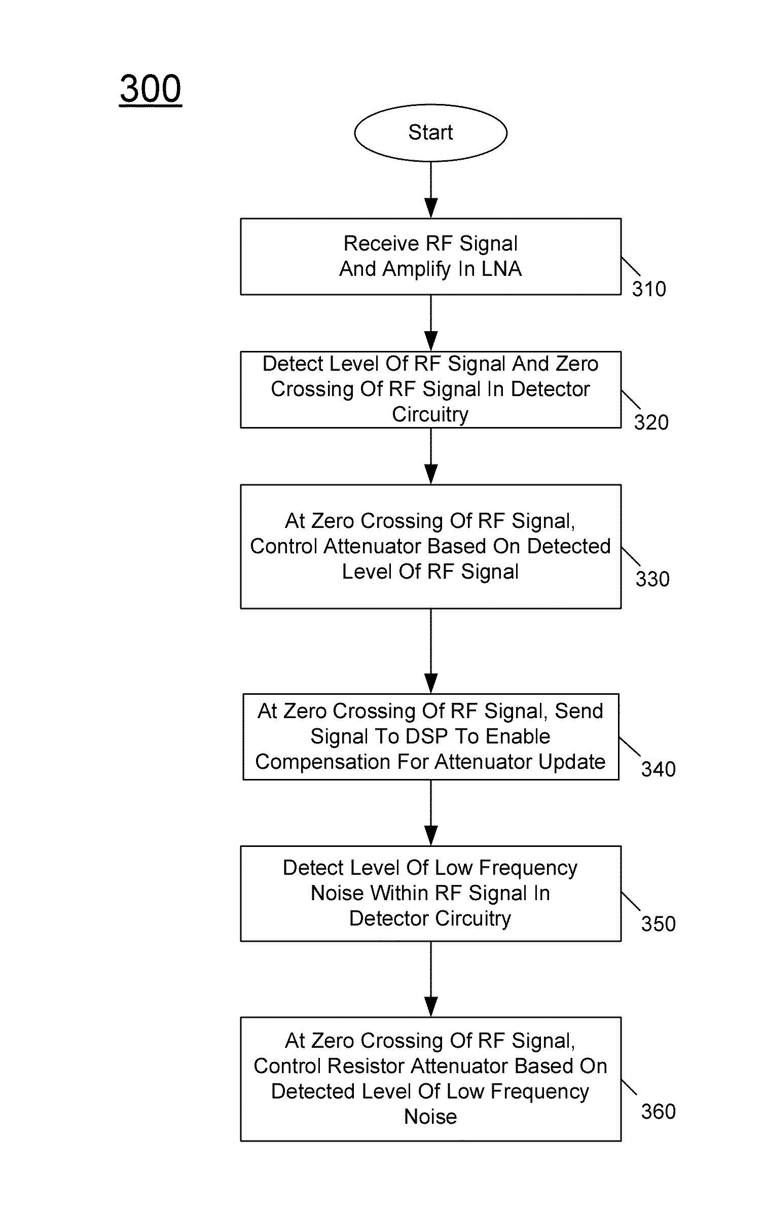
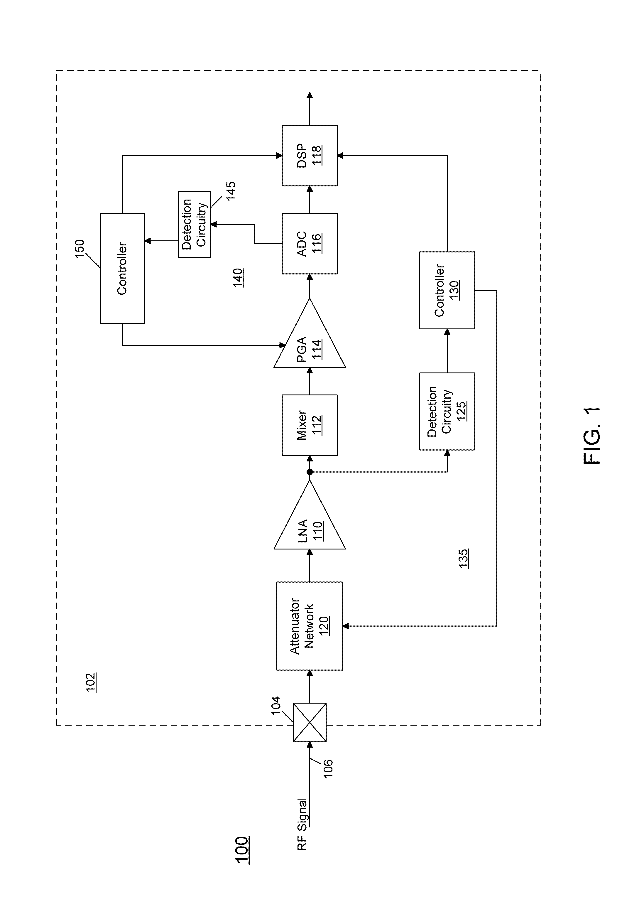
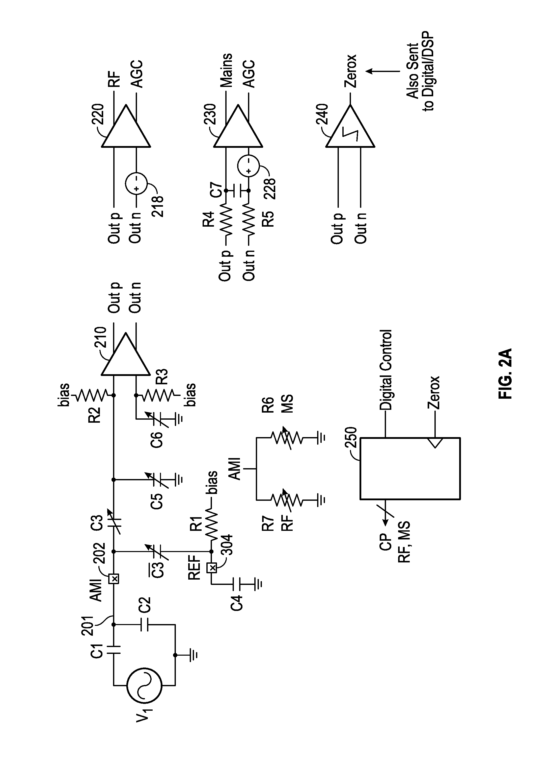
[0015]In various embodiments, a radio receiver includes circuitry to detect signal strength present across a wide range of frequencies received in the receiver and to automatically and independently attenuate and filter in at least several different ranges. In an embodiment a radio receiver, which may be configured as a single semiconductor die of an integrated circuit (IC), includes an input terminal for receiving a radio frequency (RF) signal and one or more attenuation networks coupled to the input terminal. The attenuation network(s) are controlled responsive to one or more control signals from a controller to selectively adjust at least one of a resistive attenuation to filter low frequency noise and a capacitive attenuation, which is wideband and variable to attenuate all frequencies, to apply a desired attenuation to the RF signal.

[0016]As used herein, the term “RF signal” refers to a signal having a frequency within a range of about 100 kilohertz (kHz) to several gigahertz. ...


PUM


Abstract

An apparatus includes an input terminal to receive a radio frequency (RF) signal and to communicate the RF signal to a low noise amplifier (LNA) via an input signal path, and a capacitor attenuator coupled to the input terminal to attenuate the RF signal by a controllable amount and having a first portion controllable to include a used part configured on the input signal path and an unused part coupled between the input signal path and an AC reference node, and a second portion coupled between the LNA and the AC reference node.

Description

BACKGROUND[0001]When an amplitude modulated (AM) radio frequency receiver moves near a source of low frequency noise (such as power line noise, traffic light noise, Integrated Services Digital Network (ISDN) noise, other low frequency noise and their associated harmonics), low frequency noise couples into the received AM signal, producing interference, which can sometimes be presented as a distorted audio signal including static and / or interfering channel signals. Many receivers include a low frequency “trap” circuit, including an inductor / resistor circuit, coupled to a signal input (such as a whip antenna) to filter the relatively low frequency power-line noise from the received AM radio frequency signal. However, such circuitry adds to the overall cost and size of the circuit, and the “trap” circuit degrades the received AM radio frequency signal by adding a constant degradation to the signal even when no low frequency noise is present.SUMMARY OF THE INVENTION[0002]According to on...

Claims


Application Information

Patent Timeline
IPC IPC(8): H03G3/30H04B1/12
CPCH04B1/123H03G3/3031H04B1/109H03G3/008H03G3/3068H03F3/19H03F2200/294H03F2200/451H03G3/3036
Inventor MAY, MARKHANAWALT, STEVE
Owner SILICON LAB INC
Why Eureka
Try Eureka