Microwave treatment devices and methods

a treatment device and microwave technology, applied in the field of treatment devices and delivery systems, can solve the problems of unsuitable clinical use of microwave antennas, unfavorable treatment effect, and affecting the treatment effect of patients,

Inactive Publication Date: 2014-12-04
MICROCUBE
View PDF3 Cites 59 Cited by
  • Summary
  • Abstract
  • Description
  • Claims
  • Application Information

AI Technical Summary

Benefits of technology

[0019]The present invention also comprises medical systems for steering medical components or devices in the anatomy. In one embodiment, the medical system comprises at least a first and second arm, each arm having a maneuverable distal portion and a proximal portion, where manipulation of the respective arm's proximal portion permits articulation of the arm's maneuverable distal portion independently of the other respective arm, and a medical component coupled to the first arm and extendable from the first arm's maneuverable distal portion, the medical component being engageable with the second arm's maneuverable distal portion, such that when coupled to both arms, movement of either maneuverable distal portion alters a profile or p

Problems solved by technology

Simply adding an additional modality such as mapping electrodes and the conductive wires over a microwave antenna may create a microwave antenna that is unsuitable for clinical use.
This in turn may causes problems such as burning or charring of tissue, creation of undesirable blood clots and adherence of the microwave antenna to tissue.
This in turn may create a shaped microwave field that is no longer clinically useful.
Such a shaped microwave field may also create additional safety issues by undesired microwave energy delivery to healthy tissue.
Traditionally, the desire to minimize trauma to the patient often comes at the expense of the maneuverability of the medical component when compared to a similar open surgical procedure.
Yet, such freedom is lost during minimally invasive procedures and in some open surgical procedures where the physician's access to the target site is limited due to obstructing tissue or organs (such as access

Method used


Image

  • Microwave treatment devices and methods
  • Microwave treatment devices and methods
  • Microwave treatment devices and methods

Examples


Embodiment Construction

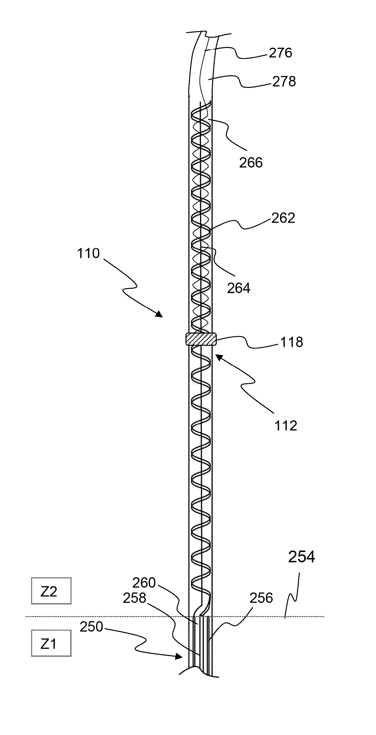
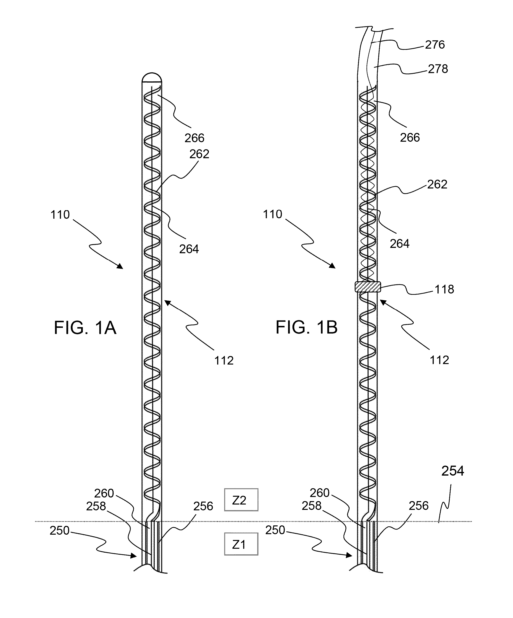
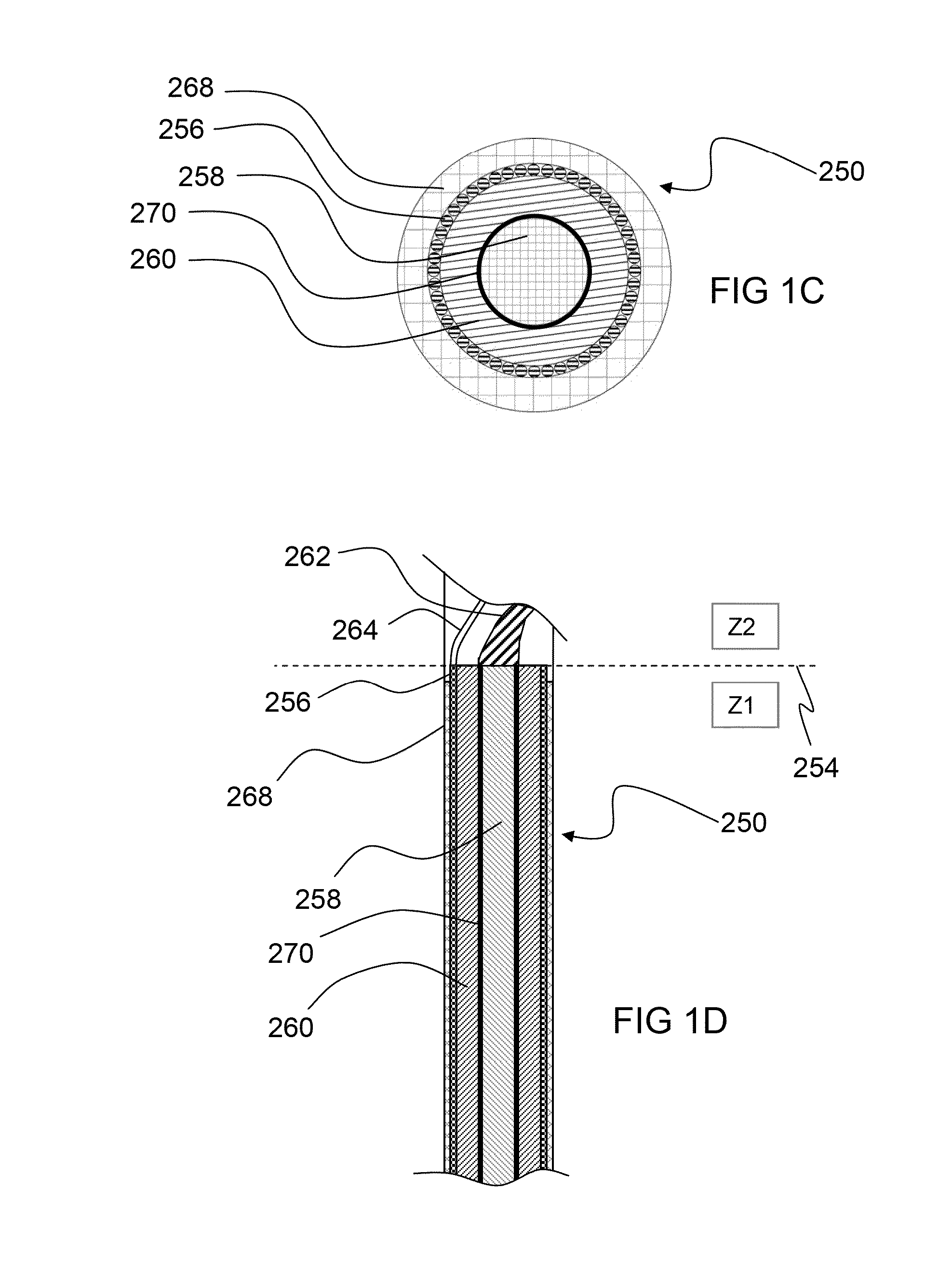
[0083]The present invention discloses devices and methods for treating tissue with microwave energy or other energy modalities. In several method embodiments, microwave energy is used for ablating tissue e.g. for treating atrial fibrillation by controlled ablation of left atrial tissue, for trating hypertension by renal denervation, etc. The systems and methods described herein are useful in a variety of medical procedures including various diagnostic and surgical procedures. In addition, the invention is also useful in open surgical procedures, minimally invasive procedures, as well as procedures performed through natural body openings.

[0084]In a significant amount of the disclosure, the heart or the renal arteries are used as examples of target organs and cardiac ablation and renal denervation procedures are used as examples of procedures that may be performed using the current invention. However, it should be noted that the various methods and devices disclosed herein may also be...


PUM


Abstract

The present invention discloses embodiments of microwave antennas and other energy delivery systems. The present invention also discloses systems and methods for the delivery of various medical components within or on a body for performing one or more medical procedures. Several embodiments herein disclose medical systems comprising a combination of one or more medical components and one or more elongate steerable or non-steerable arms that are adapted to mechanically manipulate the one or more medical components. Several embodiments of microwave antennas are disclosed that comprise an additional diagnostic or therapeutic modality located on or in the vicinity of the microwave antennas.

Description

CROSS-REFERENCE TO RELATED APPLICATIONS[0001]This application is a continuation in part of U.S. patent application Ser. No. 12 / 603,134, filed Oct. 21, 2009 which claims benefit of U.S. Provisional Patent Application Nos. 61 / 222,409, filed Jul. 1, 2009; 61 / 180,133, filed May 21, 2009; 61 / 162,241, filed Mar. 20, 2009; and 61 / 107,252, filed Oct. 21, 2008; this application is also a continuation in part of U.S. patent application Ser. No. 12 / 603,349, filed Oct. 21, 2009, which claims benefit of U.S. Provisional Patent Application Nos. 61 / 113,189, filed Nov. 10, 2008; 61 / 113,192, filed Nov. 10, 2008; 61 / 113,194, filed Nov. 10, 2008; 61 / 162,241, filed Mar. 20, 2009; 61 / 162,244, filed Mar. 20, 2009; and 61 / 222,409, filed Jul. 1, 2009; this application is also a continuation in part of U.S. patent application Ser. No. 12 / 603,077, filed Oct. 21, 2009, which claims benefit of U.S. Provisional Patent Application Nos. 61 / 222,409, filed Jul. 1, 2009; 61 / 180,133, filed May 21, 2009; 61 / 162,241, f...

Claims


Application Information

Patent Timeline
IPC IPC(8): A61B18/18
CPCA61B18/1815A61B2018/1861A61B2018/00005A61B2018/00351A61B2018/00422A61B2018/00452A61B2018/00488A61B2018/00511A61B2018/00517A61B2018/00523A61B2018/00529A61B2018/00547A61B2018/00559A61B2018/00577A61B2018/00702A61B2018/00726A61B2018/00791A61B2018/00839A61B2018/00875A61B2018/00982A61B2018/00994A61B2018/1846A61B2018/1853A61B2018/1869A61B18/20A61B2018/00023A61B2018/00029A61B2018/0044A61B2018/00494A61B2018/005A61B2018/00541A61B2018/00761A61B2018/00785A61B2018/00827A61B2018/00863A61B2018/00892A61B2018/00904A61N7/022A61B2018/0212A61B2018/00184A61B2018/00404A61B2018/00642
Inventor EMMONS, CLARENCECHU, CHUN YIUWALKE, AMRISH J.MODY, DINESH I.SHROFF, KETAN
Owner MICROCUBE
Why Eureka
Try Eureka