Memory controller and data storage device

Inactive Publication Date: 2014-12-04
THE UNIV OF TOKYO
View PDF7 Cites 56 Cited by
  • Summary
  • Abstract
  • Description
  • Claims
  • Application Information

AI Technical Summary

Problems solved by technology

This may cause problems like the increase number of repetitions of the repeat operation and wrong correction.
This technique may, however, increase the number of data read-out times from the flash memory and increase the time sp

Method used


Image

  • Memory controller and data storage device
  • Memory controller and data storage device
  • Memory controller and data storage device

Examples


Embodiment Construction

[0026]Some aspects of the invention are described below with reference to an embodiment.

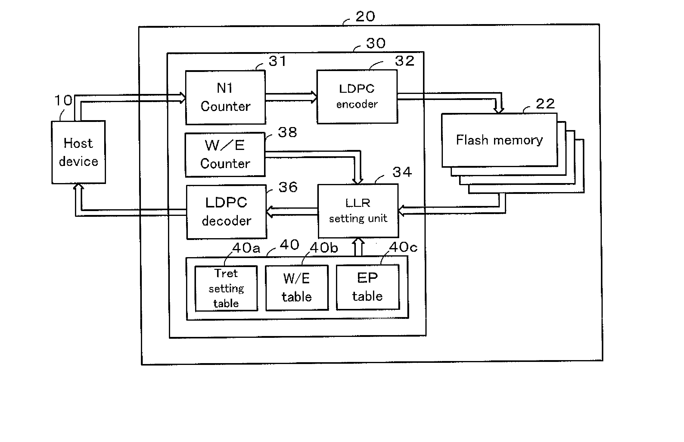
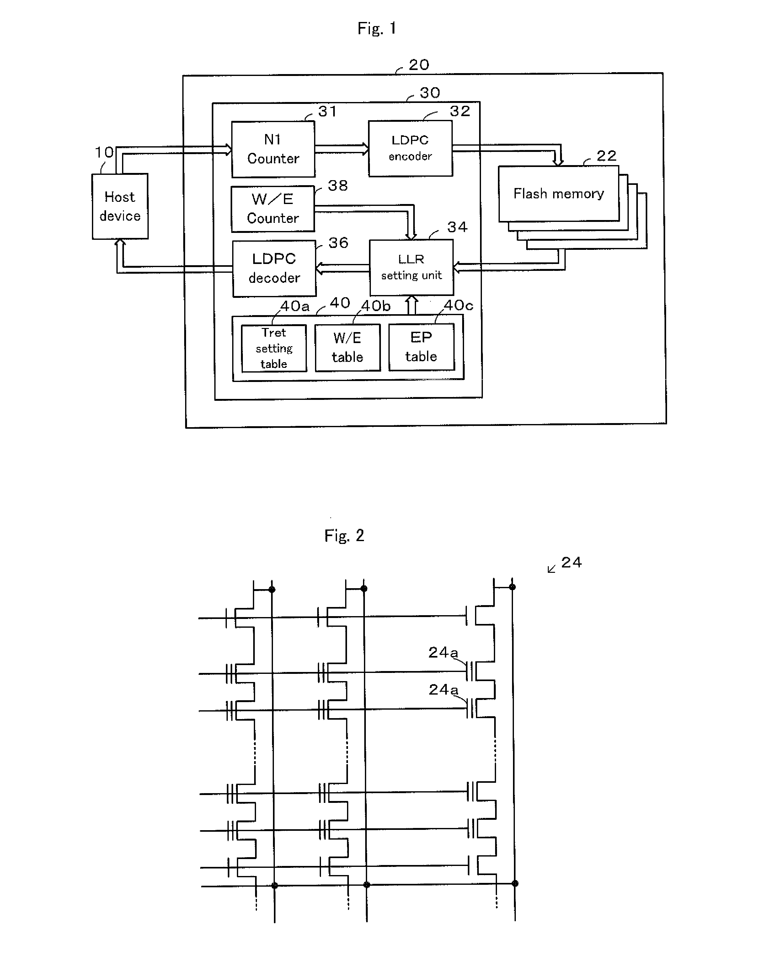
[0027]FIG. 1 is an explanatory diagram illustrating the general configuration of an SSD (Solid State Driver) 20, on which a memory controller 30 according to an embodiment of the invention is mounted to store data from a host device 10 such as a personal computer. The SSD 20 is configured as a high-capacity data storage device to store various application programs and various data, and includes flash memories 22, each configured by a NAND-type flash memory, and the memory controller 30 to control the flash memories 22.

[0028]As shown in FIG. 2, the flash memory 22 is configured by a NAND-type flash memory including a flash memory cell array 24 comprised of a plurality of flash memory cells 24a, each having a change in threshold voltage by electron injection into the floating gate or electron withdrawal from the floating gate. The flash memory 22 includes a row decoder, a column decoder and a sense...


PUM


Abstract

A memory controller sets an estimated cell error ratio CERest based on an estimated retention time Tret obtained from a calculated bit error ratio BER, a number of rewrite times NW/E, data Datatag of a target cell and data Dataadj of memory cells surrounding the target cell, sets an upper-level page LLRu and a lower-level page LLRl with regard to all bits of read-out one-page data using the set estimated cell error ratio CERest and performs error correction and decoding of data read out from a flash memory using the settings of the upper-level page LLRu and the lower-level page LLRl. This improves the error correction capability, while suppressing an increase in processing time.

Description

TECHNICAL FIELD[0001]The present invention relates to a memory controller and a data storage device. More specifically, the invention relates to a memory controller and a data storage device including the memory controller configured such as to, in the case of writing data into a non-volatile memory having a plurality of non-volatile memory cells, encode the data to be written into a specified code which is decodable by an operation using a log-likelihood ratio and control the non-volatile memory to store the encoded code data into the non-volatile memory, and in the case of reading data from the non-volatile memory, control the non-volatile memory to read out code data of a predefined size from the non-volatile memory and decode the code data by iterative processing based on the probability using the log-likelihood ratio.BACKGROUND ART[0002]A technique of performing error correction for data output from a flash memory and outputting the error-corrected data to a host device has bee...

Claims


Application Information

Patent Timeline
IPC IPC(8): G06F11/07
CPCG06F11/076G06F11/1048G06F11/073
Inventor TAKEUCHI, KENTANAKAMARU, SHUHEI
Owner THE UNIV OF TOKYO
Why Eureka
Try Eureka