Method for lowering and raising a wind turbine blade

Active Publication Date: 2014-12-11
INVENTUS HLDG
View PDF3 Cites 24 Cited by
  • Summary
  • Abstract
  • Description
  • Claims
  • Application Information

AI Technical Summary

Benefits of technology

[0016]It is an object of this invention to provide a method for raising and lowering a wind turbine blade without causing damage to the blade. More specifically, it is an object of the invention to provide a lifting system that allows the use of tag lines to keep a blade from being blown against the tower while bei

Problems solved by technology

The extreme length and weight of a blade, and its aerodynamic shape and structural characteristics, make the job of lowering and raising a blade from a turbine in the field a difficult and exacting task.
In addition, blades must be removed from wind turbines situated in areas in which accessibility is limited, and in which the local terrain may not permit the ingress or egress of larger vehicles, such as large cranes.
Moreover, because wind turbines are designed to be situated in areas of more-or-less constant pre

Method used


Image

  • Method for lowering and raising a wind turbine blade
  • Method for lowering and raising a wind turbine blade
  • Method for lowering and raising a wind turbine blade

Examples


Embodiment Construction

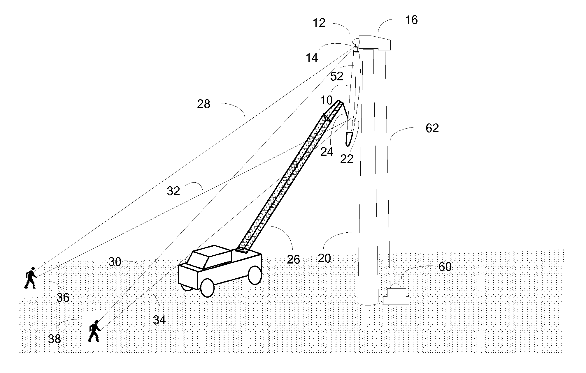
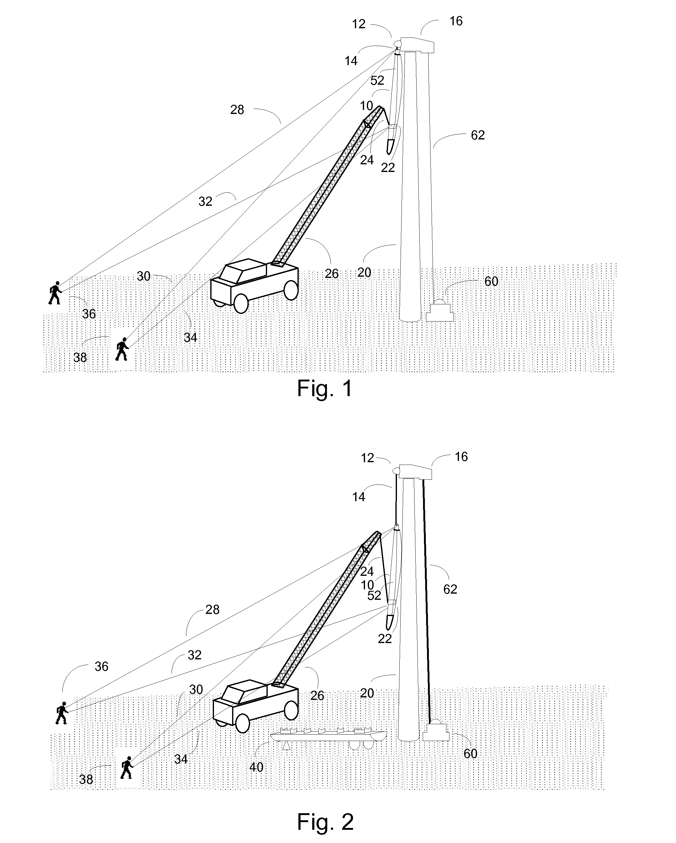
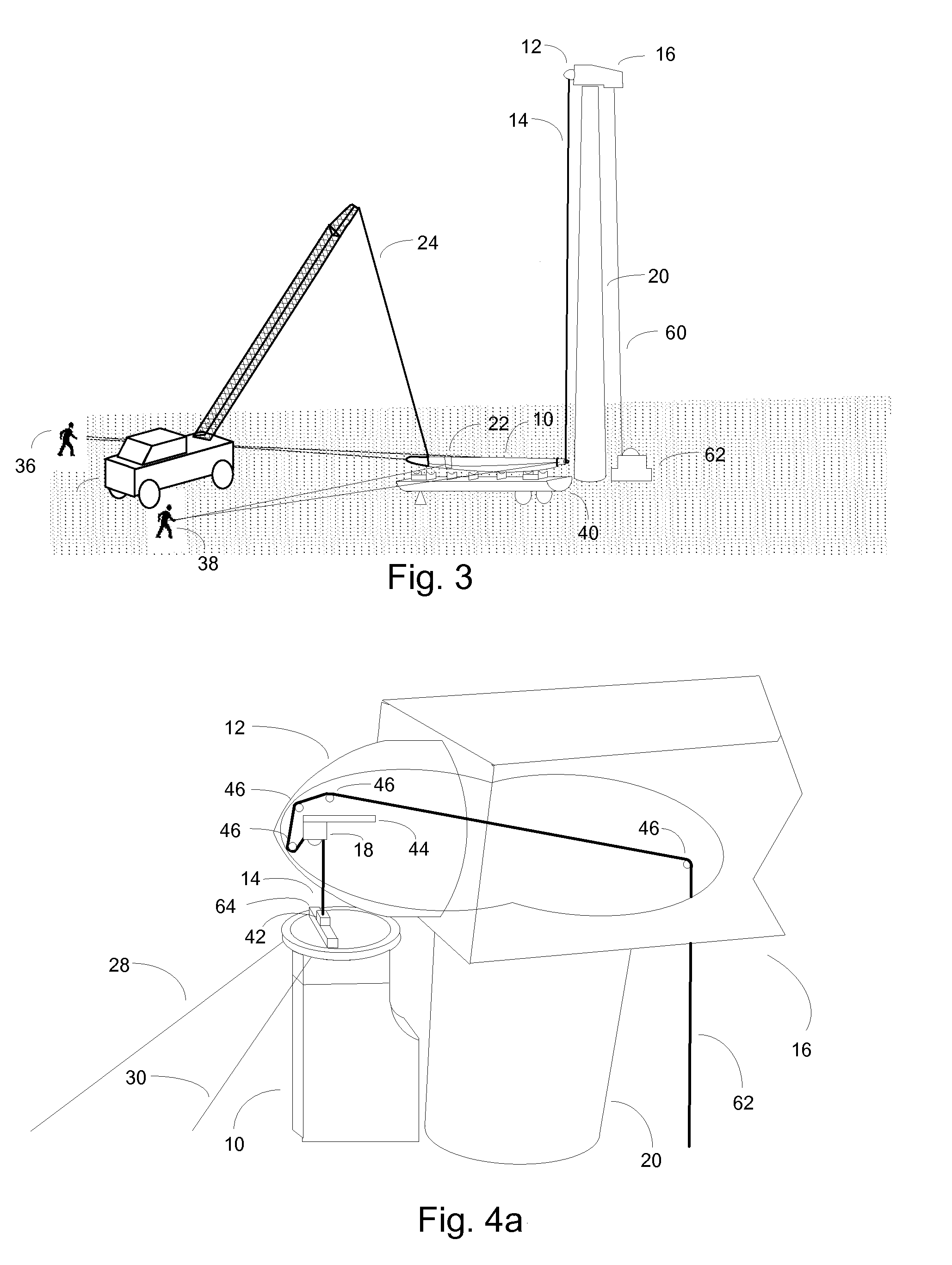
[0030]Referring to FIG. 1, a blade 10 has been detached from a hub 12 and is being supported by main cable 14 which extends downward from a nacelle 16 at the top of tower 20. Cable 14 is attached to a traction hoist or winch which, in a preferred embodiment, is situated in nacelle 16. Slack main cable 62 has no tension on it, and feeds down from wind turbine tower 20 where it is taken up by take-up spool 60. In other embodiments the take-up spool may also be located in the nacelle, or the winch may be situated at ground level rather than within nacelle 16. To hold the blade and lower it from the hub, the winch is used to provide the hoisting power.

[0031]A tip end shoe 22 fits around the lower section of the blade, and is held in place with a suspender cord 52 that extends longitudinally along the blade between the tip end shoe 22 and a collar 54. The tip end shoe forms the lower part of a harness that holds the blade at a desired orientation. In a preferred embodiment, with a blade ...


PUM

PropertyMeasurementUnit
Weightaaaaaaaaaa
Lengthaaaaaaaaaa
Distanceaaaaaaaaaa

Abstract

A method of lowering a wind turbine blade after removal from a wind turbine lowers the blade in a vertical position to a point near the ground, and rotates it to a horizontal position for emplacement on a cradle. A winch is situated in the nacelle of the wind turbine. A cable extends downward from the winch to the blade root where it may be secured to a load cell. A tip end shoe is placed around the lower portion of the blade, and includes a crane hook receiving component that is used when the blade orientation is being changed. Tag lines are attached to the root and the tip end shoe, and extend to points on the ground where technicians manipulate them to prevent the blade from being blown into the tower.

Description

CROSS-REFERENCE TO RELATED APPLICATION[0001]This Non-provisional Utility application claims priority to U.S. Provisional Patent Application Ser. No. 61 / 831,319, filed on Jun. 5, 2013.BACKGROUND[0002]Wind turbines are rapidly becoming a significant source of electrical power throughout the United States and in the world. A typical wind turbine consists of an electrical generator mounted in a nacelle atop a tower that may be 60 or more meters tall. The generator is powered by wind which rotates turbine blades. The turbine blades, which may be up to 50 or more meters in length and weigh upwards of 1900 kg, are mounted to a hub at the forward end of the nacelle. Typically, three blades are used, and a gearbox converts the relatively slow turbine revolution rate to a faster rate of revolutions suitable for the generator.[0003]As with most mechanical machinery, periodic maintenance, refurbishing or repair is needed for wind turbines, including the occasional need to repair or refurbish a ...

Claims


Application Information

Patent Timeline
IPC IPC(8): B23P15/04
CPCB23P15/04F05B2230/61F05B2230/70B66C23/207F03D80/50Y10T29/49318F03D1/0658Y02E10/72Y02P70/50
Inventor LOHAN, MARTIN E.PANDER, HENRIKBRAKE, DANIEL M.
Owner INVENTUS HLDG
Why Eureka
Try Eureka