Bicycle handlebar assembly with integrated oleo-hydraulic controls

a technology of oleohydraulic control and handlebar, which is applied in the direction of cycle control system, steering device, cycle equipment, etc., can solve the problems of reducing braking performance, oleohydraulic group can be a hindrance to cyclists, appearance is less pleasing, etc., and achieves a large piston displacement, large bulk, and greater bulk

Active Publication Date: 2014-12-11
CAMPAGNOLO SRL
View PDF16 Cites 6 Cited by
  • Summary
  • Abstract
  • Description
  • Claims
  • Application Information

AI Technical Summary

Benefits of technology

[0018]Preferably, the piston is hinged to the control lever in an intermediate position between the pin and the attachment position of the brake cable. The reciprocal positions on the control lever of the pin (fulcrum of the lever), of the brake cable (point of application of the driving force) and of the piston (point of application of the resistant force) are the typical ones of a so-called second class lever, in which the resistant force obtained is greater than the driving force applied, whereas, vice-versa, the movement of the point of application of the driving force is greater than the movement of the point of application of the resistant force. This configuration is thus particularly suitable for obtaining high pressures of the oil in the cylinder with small movements, since oil is much less compressible and therefore large displacements of the piston are not necessary.
[0019]Alternatively, the reciprocal positions on the control lever could be such as to configure a first class lever, with the pin in intermediate position between the brake cable and the piston. This solution, however, is not preferred, since in order to ensure the same mechanical advantage it requires greater bulk: the driving and resistant lever arms are one after the other and thus determine a larger bulk with respect to the second class lever configuration, where the maximum bulk is given by just the driving arm.
[0020]Preferably, the oleo-hydraulic cylinder is provided with two parallel ears, in which two holes are formed for the engagement of the pin. Thanks to this characteristic, the engagement between control lever and cylinder is direct, and therefore the forces transmitted from the brake cable to the piston do not pass through the material of the handlebar rod, which therefore does not need to be sized to withstand additional forces due to the presence of the cylinder.
[0021]Even more preferably, the handlebar rod comprises two holes at the holes in the ears of the cylinder, the pin being engaged both in the holes in the ears and in the holes in the handlebar rod. In this way, the pin contributes to the solidity of the coupling between cylinder and handlebar rod.
[0022]Preferably, the handlebar assembly comprises a control adjustment device between the control lever and the piston. It is thus possible to adjust the action on the piston and thus to adjust the pressure of the oil depending on the traction of the brake cable. More preferably, the control adjustment device comprises a threaded shank, mounted on the piston and in screwing engagement in a threaded seat formed in a cylinder rotatably mounted on the control lever. This simple device allows easy and precise adjustment.
[0023]Preferably, the handlebar assembly comprises a cable adjustment device between the brake cable and the control lever. It is thus possible to adjust the action on the control lever and thus adjust the pressure of the oil depending on the traction of the brake cable.

Problems solved by technology

In this way, however, oleo-hydraulic groups can be a hindrance to the cyclist while the bicycle is in use, due to their bulk, as well as making its aesthetic appearance less pleasing.
The Applicant has realised, however, that oleo-hydraulic controls directly associated to the brake lever do not have problems of bulk only if the size of the cylinders is contained within fairly low limits; in practice, the designer is forced to use very small cylinders, which can reduce braking performance, or to accept a bulk that is still inconvenient.

Method used


Image

  • Bicycle handlebar assembly with integrated oleo-hydraulic controls
  • Bicycle handlebar assembly with integrated oleo-hydraulic controls
  • Bicycle handlebar assembly with integrated oleo-hydraulic controls

Examples


Embodiment Construction

)

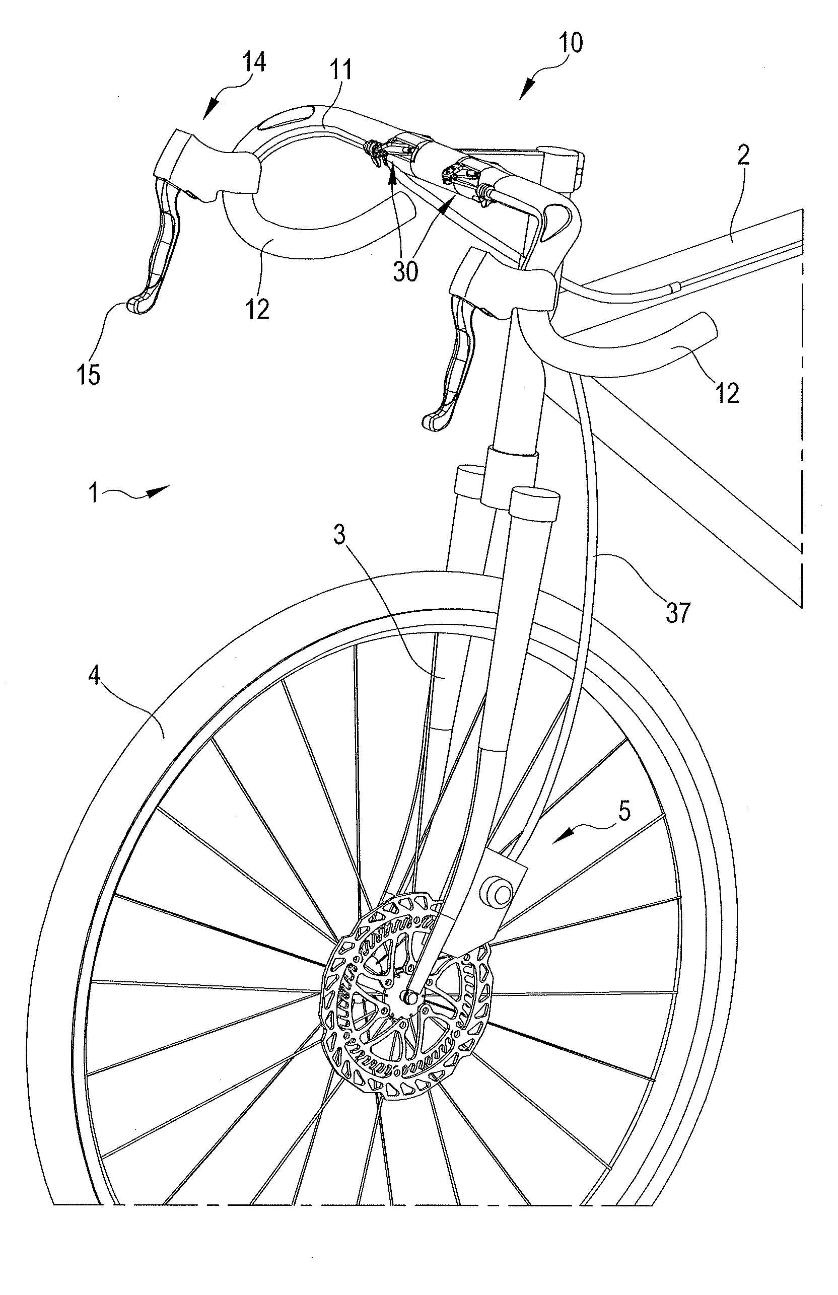
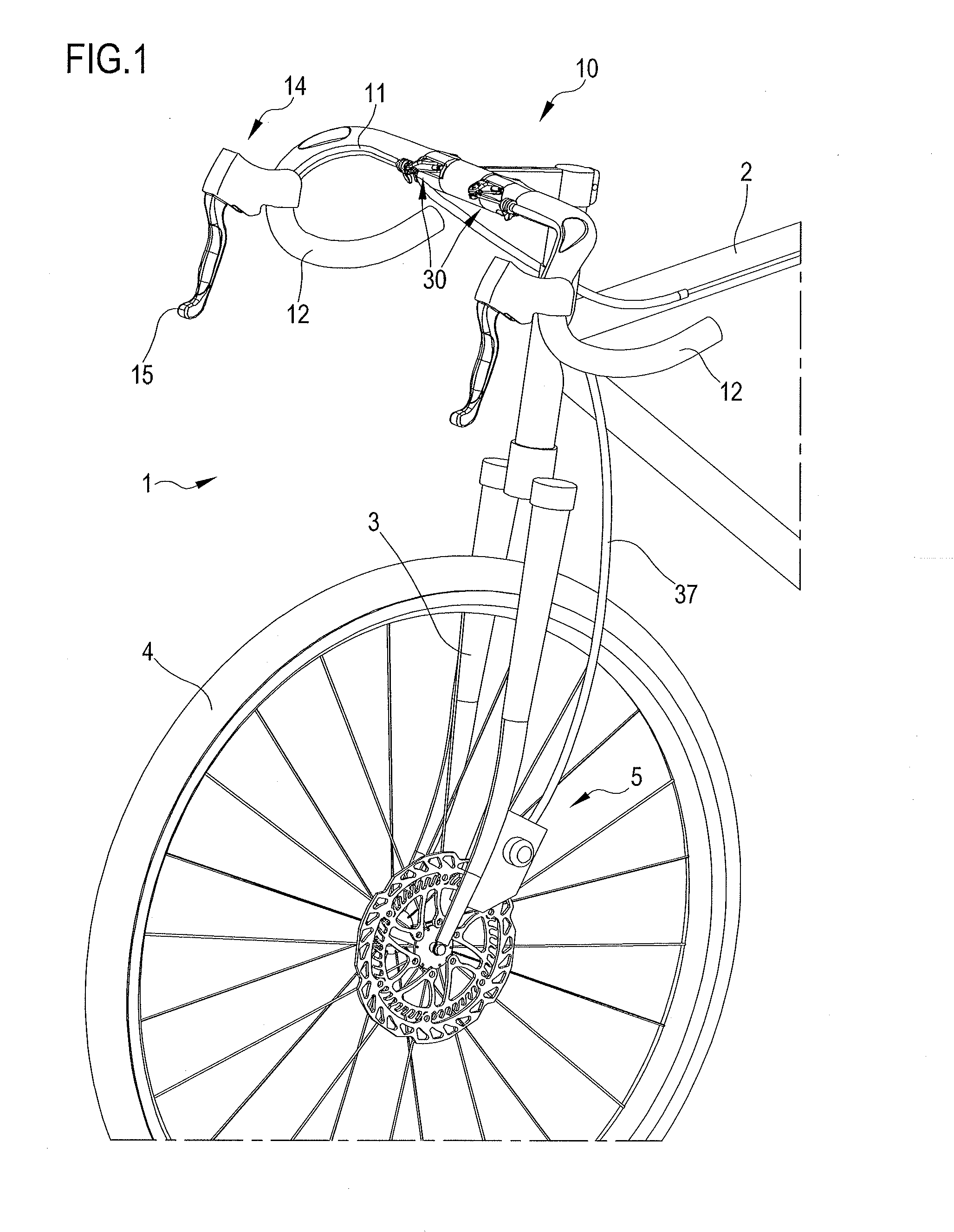
[0035]In the figures, reference numeral 1 wholly indicates a high-performance bicycle, of which in FIG. 1 it is possible to see at least partially a frame 2, a fork 3 and a front wheel 4. The bicycle 1 is provided with disc brakes 5, the front brake of which can be seen in the figures.

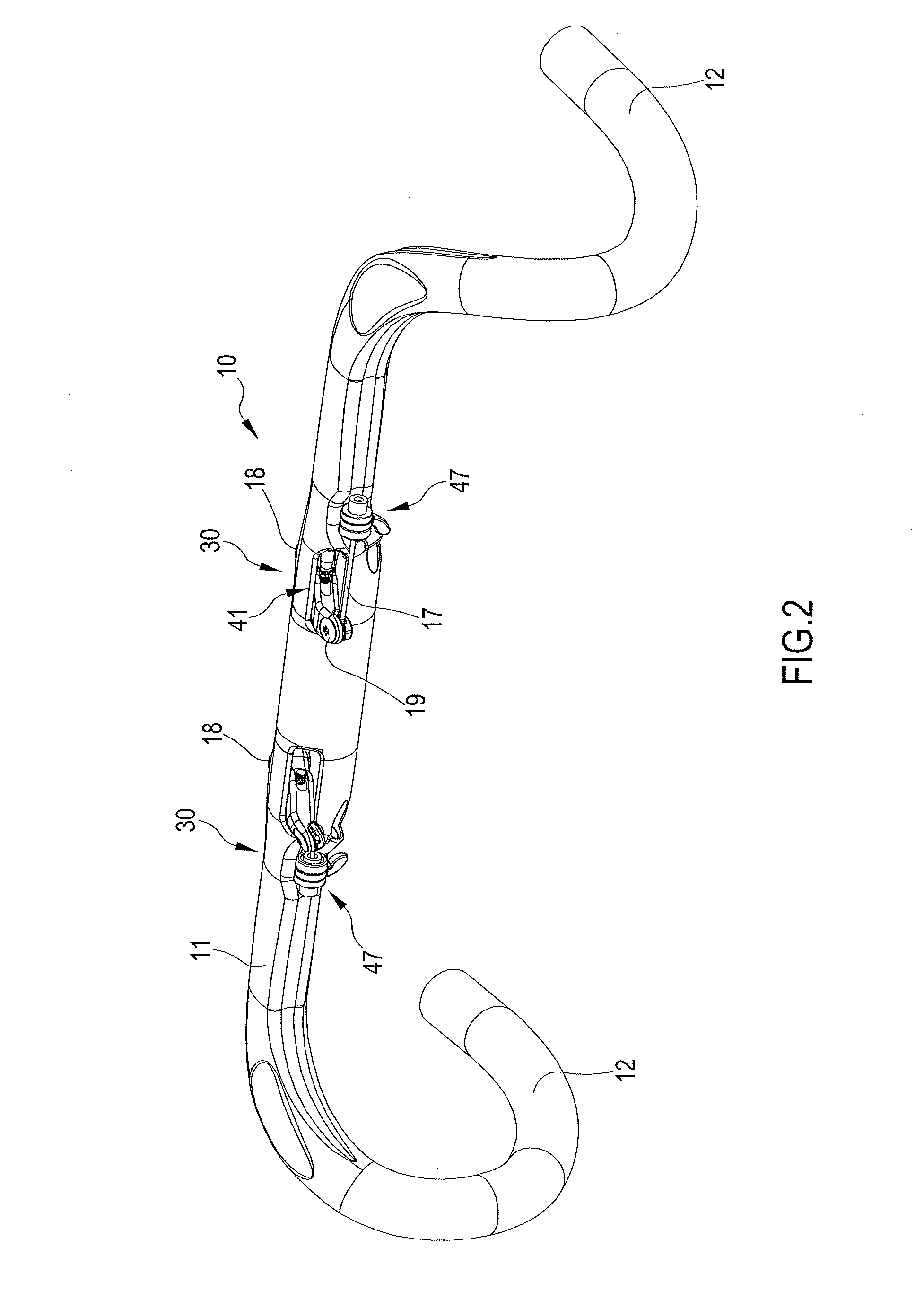
[0036]The fork 3 has a handlebar assembly 10 mounted on it, in accordance with the invention. The handlebar assembly 10 comprises a handlebar rod 11 provided at its two ends with respective handgrips 12, for example of the curved type as shown in the figures.

[0037]The handlebar rod 11 is preferably made hollow from composite material, obtained by moulding from a matrix of polymeric material in which structural fibres (for example carbon fibres or similar) are included.

[0038]In the handlebar rod 11, in a central area thereof, two oleo-hydraulic groups are housed, both indicated with 30, each for controlling one of the two brakes of the bicycle 1. The oleo-hydraulic groups 30 are housed inside the handl...


PUM


Abstract

The bicycle handlebar assembly comprises a handlebar rod and at least one oleo-hydraulic group for controlling on-board bicycle equipment; the oleo-hydraulic group is housed inside the handlebar rod.
The internal housing in the handlebar rod overcomes any problems of bulk of the oleo-hydraulic group. Moreover, thanks to the relatively large size of the handlebar rod, the dimensional constraints imposed on the designer are much less stringent with respect to controls associated directly to the brake lever; it is thus relatively easy to make controls capable of exerting very large forces.

Description

CROSS REFERENCE TO RELATED APPLICATION(S)[0001]This application claims the benefit of Italian Application No. MI2013A000950, which was filed on Jun. 10, 2013, and is incorporated herein by reference as if fully set forth.FIELD OF INVENTION[0002]The present invention relates to a bicycle handlebar assembly.BACKGROUND[0003]In modern bicycles, in particular in high-performance ones, it is becoming increasingly common to use on-board equipment that uses oleo-hydraulic controls. This is the case for example of disc braking systems, in which the force necessary to obtain adequate braking by the closing of the calipers on the discs is too high to be exerted with the usual cable systems, controlled by the cyclist's hands. With these braking systems, therefore, the force exerted by the cyclist's hand is transferred to an oleo-hydraulic group; more specifically, a piston is actuated that places oil inside a cylinder under pressure. The pressurised oil is then transferred through suitable tube...

Claims


Application Information

Patent Timeline
Patent Type & Authority Applications(United States)
IPC IPC(8): B62K21/12B62K23/06
CPCB62K23/06B62K21/12B62K23/02B62L3/023B62M25/08Y10T74/20256Y10T74/2028
Inventor MEGGIOLAN, MARIO
Owner CAMPAGNOLO SRL
Why Eureka
Try Eureka