Door handle assembly for a motor vehicle
a technology for motor vehicles and handle assemblies, which is applied in the direction of mechanical equipment, carpet fasteners, and lock applications, etc., can solve the problems of significant risks to a passenger in the motor vehicle, unintentional opening of the door of the motor vehicle, and unintended movement of the handle, so as to achieve simple and cost-effective
- Summary
- Abstract
- Description
- Claims
- Application Information
AI Technical Summary
Benefits of technology
Problems solved by technology
Method used
Image
Examples
first embodiment
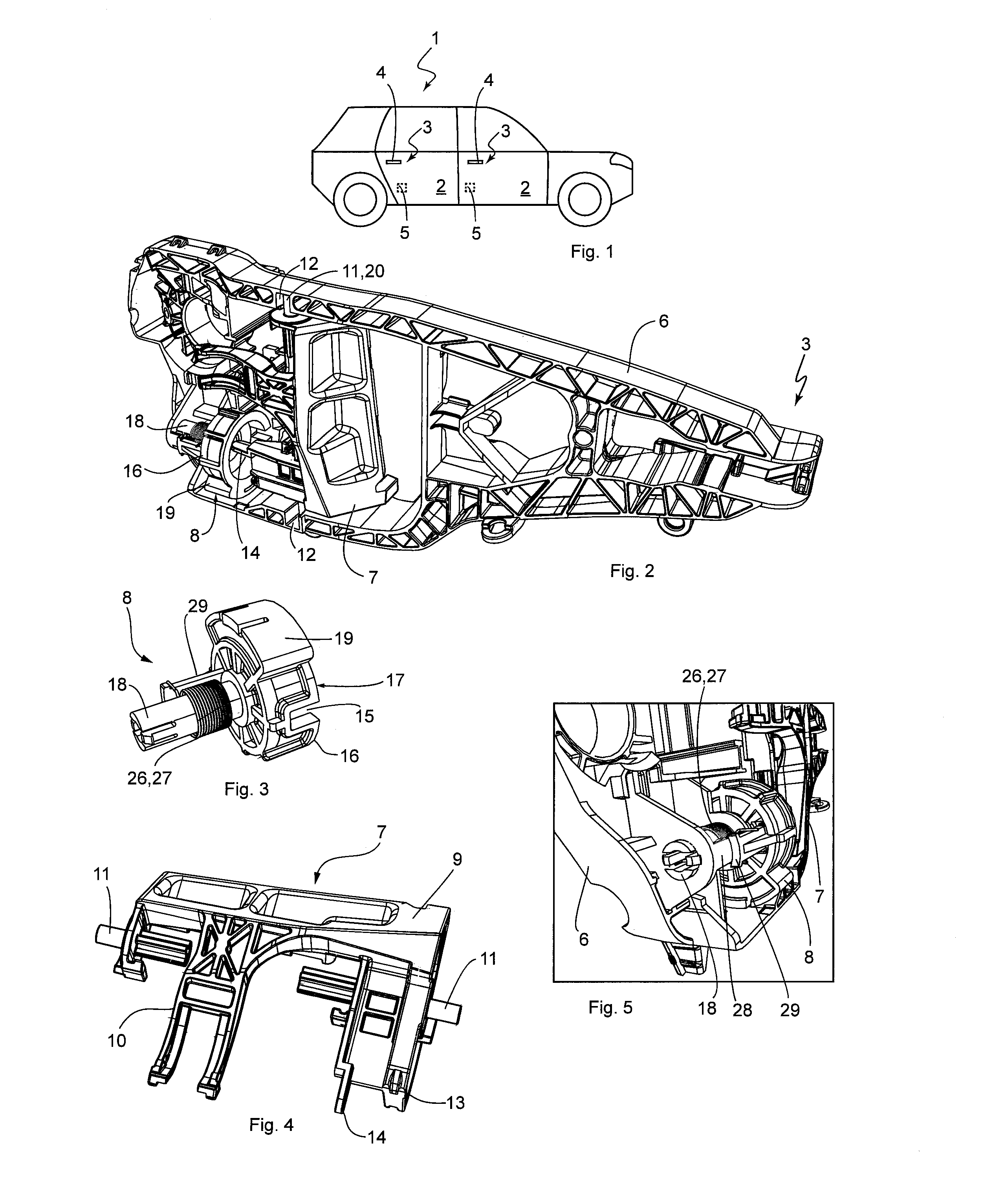
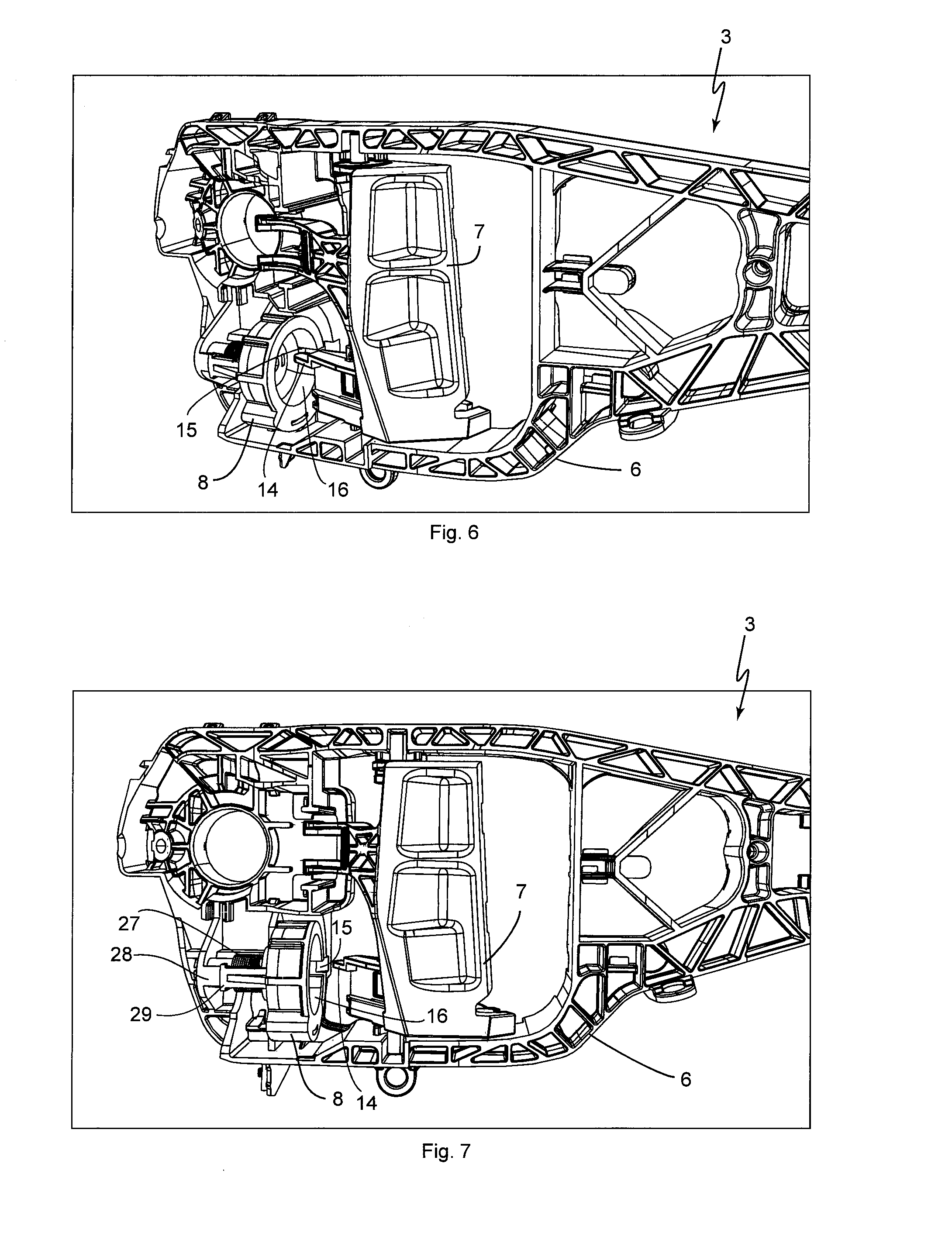
[0051]In the door handle assembly 3, the locking device 8 is designed in sections as a hollow cylinder 16, as is shown in FIGS. 2 and 6-9. The movement cavity 15 is formed in the shell of the hollow cylinder 16, running in the longitudinal direction, and represents a type of incision in the open front end 17 of the hollow cylinder 16 (see FIG. 3). In other words, the movement cavity 15 of the locking device 8, starting at the open front end 17 of the hollow cylinder 16, is formed running in the longitudinal direction thereof.
[0052]A state of the door handle assembly 3 is shown in FIG. 2, in which the locking device 8 is in its normal operating position and is thus not activated. Furthermore, in this state, the coupling device 7 is disposed in the rest position, because the operating handle is not actuated. In the normal operating position of the locking device 8, when the operating handle 4 is not actuated, the movement projection 14 extends into the open front end 17 of the hollow ...
second embodiment
[0057]With the door handle assembly 3′, the locking device 8′ is designed in sections as a disk element 23, as is shown, for example, in FIGS. 11 and 12. The movement cavity 15′ is formed on one of the two lateral surfaces of the disk element 23 as a guide channel 24, open on one side (see FIGS. 12 and 18, by way of example), for guiding the movement projection 14′ when the locking device 8′ is in its normal operating position. The guide channel 24 extends on the lateral surface of the disk element 23, offset to its center.
[0058]FIGS. 10 and 15 each show a state of the door handle assembly 3′, in which the locking device 8′ is disposed in its normal operating position, and the coupling device 7′ is in the rest position, due to the operating handle 4 not being actuated. The movement projection 14′ of the locking device 8′ is disposed in the normal operating position, outside of the guide channel 24 when the operating handle 4 is not actuated. In the state shown in FIGS. 10 and 15, th...
PUM
 Abstract
Description
Claims
Application Information
 - R&D
- Intellectual Property
- Life Sciences
- Materials
- Tech Scout
- Unparalleled Data Quality
- Higher Quality Content
- 60% Fewer Hallucinations
Browse by: Latest US Patents, China's latest patents, Technical Efficacy Thesaurus, Application Domain, Technology Topic, Popular Technical Reports.
© 2025 PatSnap. All rights reserved.Legal|Privacy policy|Modern Slavery Act Transparency Statement|Sitemap|About US| Contact US: help@patsnap.com


