Method of Detecting a Leak in a Membrane of a Roof

a leak detection and roof technology, applied in the direction of resistance/reactance/impedence, instruments, roofing, etc., can solve the problems of faulty application of the membrane system, design deficiencies, and premature failure, and achieve the effect of low cos

Active Publication Date: 2014-12-11
DETEC SYST
View PDF5 Cites 26 Cited by
  • Summary
  • Abstract
  • Description
  • Claims
  • Application Information

AI Technical Summary

Benefits of technology

[0013]Preferably the intervening layer has a resistance level in the range 1×10² to 1×10⁷ ohms per square. This can be obtained by providing a loading of the conductive filler which lies in the range from four to thirty percent (4% to 30%). This level of resistance provides a conductivity which is very low in comparison with other materials since the current flow can be detected at very low levels. This loading of the filler can be achieved without interfering with the other properties of the carrier material and at relatively low cost.
[0014]Preferably the electric potential at the roof substrate is provided by a conductor in electrical connection with the intervening layer. In this way there is no requirement to connect the potential difference to roof substrate itself. Thus the conductor can be applied onto the roof substrate as a metal plate of an elongate conductor and covered with the intervening layer.

Problems solved by technology

The failure to detect, find and correct membrane defects during and as soon after its installation as possible, can cause premature failure.
Problems include design deficiencies, faulty application of the membrane system and damage by subsequent tradesmen.
Roof designs incorporating a waterproofing membrane under a green roof, insulation layer, wear-course, or topping slab greatly exacerbate the problem of leak locating.
Accumulated water in insulation compromises its thermal properties.
Accumulated water in construction materials can cause rotting and other damage which is very costly to repair.

Method used


Image

  • Method of Detecting a Leak in a Membrane of a Roof
  • Method of Detecting a Leak in a Membrane of a Roof

Examples


Embodiment Construction

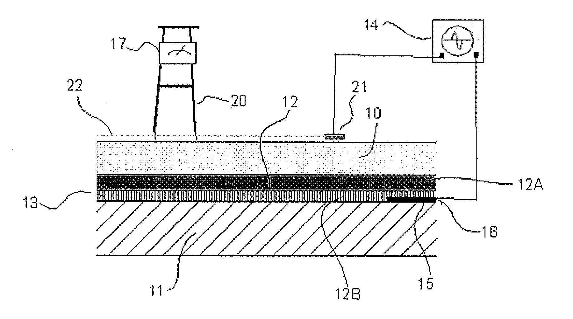
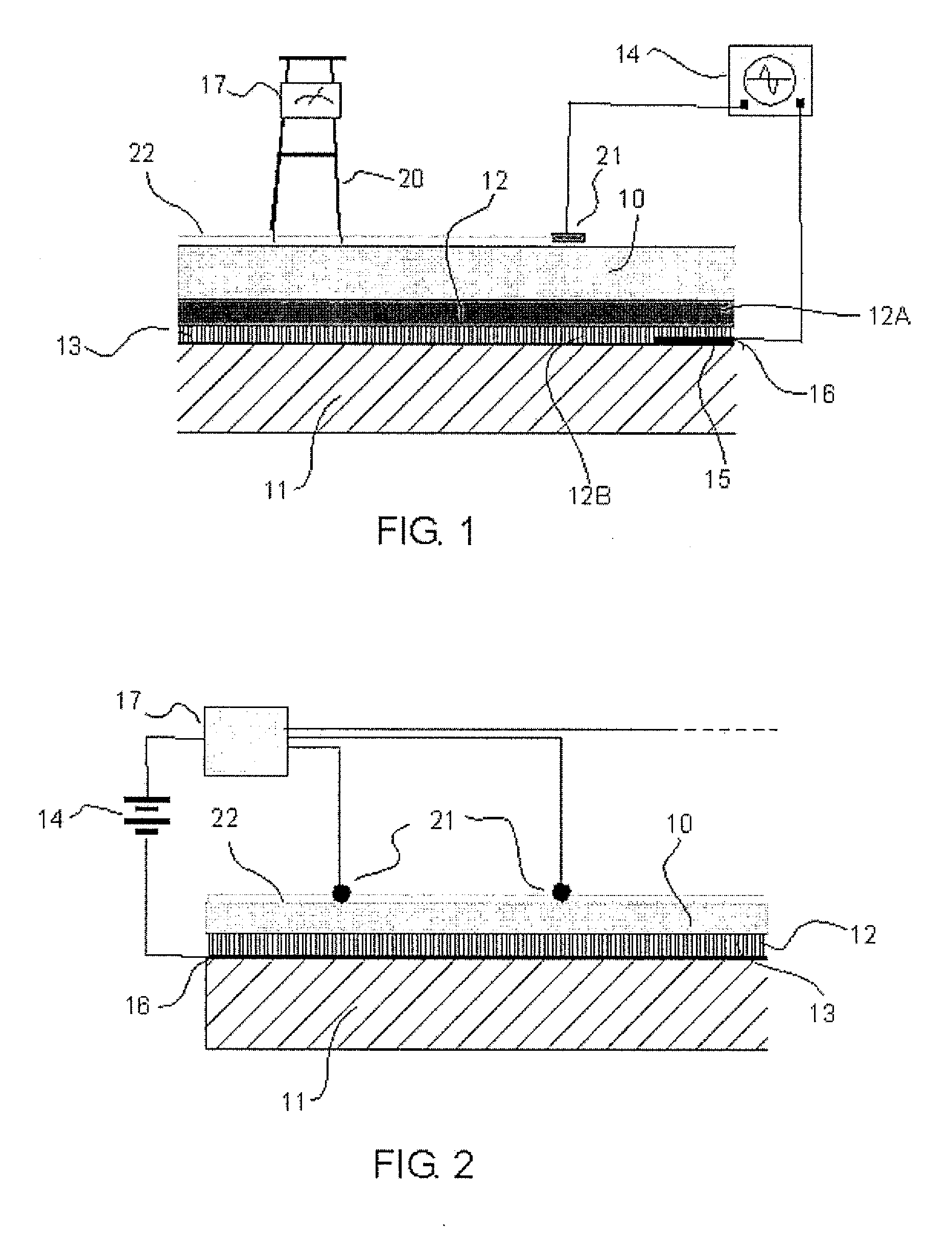
[0027]In the method shown in the Figures there is provided a water impermeable membrane 10 applied onto a generally horizontal roof support substrate 11.

[0028]The membrane 10 is applied to the roof substrate by an intervening layer 12 therebetween where the intervening layer 12 includes electrically conductive material 13. In FIG. 1, the intervening layer includes a primer layer 12A and an adhesive layer 12B where the adhesive layer contains an adhesive material. The intervening layer 12 thus comprises an adhesive material that is chemically compatible with the membrane 10 together with the conductive filler material 13 to render the layer immediately on top of the substrate electrically conductive.

[0029]An electric potential at the roof substrate is provided by a conductor 15 in electrical connection with the intervening layer 12B and connected to one terminal of a generator 14. The conductor 15 in FIG. 1 comprises a metal plate 16 applied onto and attached to the roof substrate an...


PUM

PropertyMeasurementUnit
water impermeableaaaaaaaaaa
electrical potentialaaaaaaaaaa
currentaaaaaaaaaa

Abstract

In a method of detecting a leak in a water impermeable membrane applied on a roof substrate, an electrical potential is created between a conductive detector on top of the membrane and the roof substrate causing current to flow between the roof substrate and the conductive detector through moisture in any leak in the membrane. The membrane is attached to the roof support substrate by an intervening layer therebetween which can be a primer or an adhesive layer which is caused to be electrically conductive by the addition an electrically conductive material. This allows the conductor on the roof substrate to which the potential difference is applied to be attached onto the roof substrate and covered by the layer underneath the membrane.

Description

[0001]This invention relates to a method of detecting a leak in a water impermeable membrane of a roof using low voltage to generate a current through any defects which can be detected by sensors on top of the membrane.BACKGROUND OF THE INVENTION[0002]The failure to detect, find and correct membrane defects during and as soon after its installation as possible, can cause premature failure. Problems include design deficiencies, faulty application of the membrane system and damage by subsequent tradesmen. Roof designs incorporating a waterproofing membrane under a green roof, insulation layer, wear-course, or topping slab greatly exacerbate the problem of leak locating. The early detection of leaks in waterproof membranes is crucial during construction and for effective roof maintenance. Leaks in conventional roof assemblies allow moisture to accumulate under the membrane in the underlying components such as protection boards and insulation. Accumulated water in insulation compromises...

Claims


Application Information

Patent Timeline
Patent Type & Authority Applications(United States)
IPC IPC(8): G01N27/04
CPCG01N27/04G01N27/20G01M3/40E04D13/006
Inventor VOKEY, DAVID E.JORDAN, WALTER ISAAC
Owner DETEC SYST
Why Eureka
Try Eureka