
Electronic control unit having integrated circuit element and standalone test unit for integrated circuit element

a technology of integrated circuit elements and test units, which is applied in the direction of electronic circuit testing, measurement devices, instruments, etc., can solve the problems of difficulty in quick detail checks, affecting the reliability of electronic control units, and unable to individually check the various combination circuits, etc., to achieve high reliability, improve reliability, and high accuracy

Active Publication Date: 2014-12-11
MITSUBISHI ELECTRIC CORP
View PDF4 Cites 22 Cited by
  • Summary
  • Abstract
  • Description
  • Claims
  • Application Information

AI Technical Summary

Benefits of technology

The present invention provides an electronic control unit with a built-in self-test circuit that includes a self-test control block, scan chain circuits, and mask circuitry. The integrated circuit element can select between two combinations of scan chain circuits for self-testing, and an external test can be performed on the built-in self-test control block during shipment inspection without needing to generate a diagnostic pulse-train signal. This improves the reliability of the integrated circuit element and ensures accurate and reliable self-testing.

Problems solved by technology

However, no detail checks are made individually on the various combination circuits, with the microprocessor and the monitoring and control circuit section being halted.
In particular, it is difficult to perform quickly the detail checks within a limited permissible time at start of operation; therefore such detail checks have been unachieved.
Therefore, a detail check for various combination circuits cannot be performed by making use of these scan pass circuits (scan chain circuits), with the integrated circuit element assembled into the actual electronic control unit.

Method used


Image

  • Electronic control unit having integrated circuit element and standalone test unit for integrated circuit element
  • Electronic control unit having integrated circuit element and standalone test unit for integrated circuit element
  • Electronic control unit having integrated circuit element and standalone test unit for integrated circuit element

Examples


embodiment 1

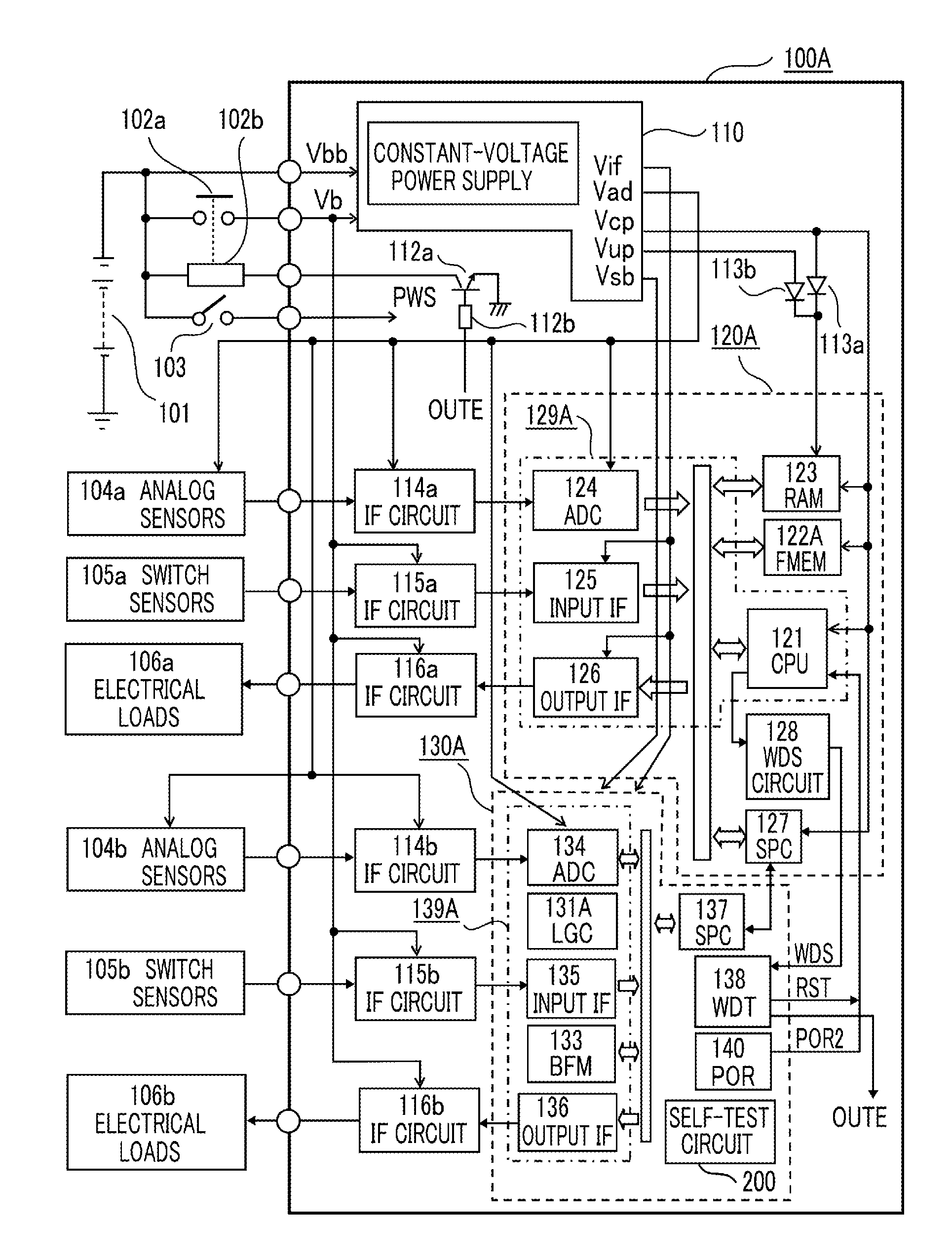
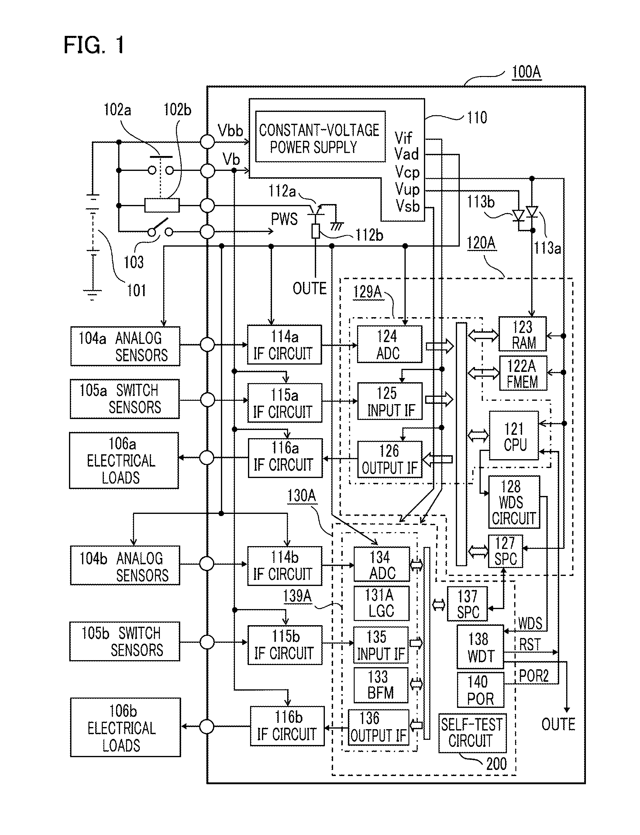
[0035]The configuration of an electronic control unit having integrated circuit elements, according to an embodiment 1 of the present invention will be described in detail below with reference to FIG. 1 showing an overall configuration diagram of the electronic control unit. Referring to FIG. 1, an electronic control unit 100A is mainly constituted with late-described components: a constant-voltage power supply circuit 110; a main control circuit section that is a first integrated circuit element 120A (hereinafter, may also be referred to as a main control circuit section 120A); and a monitoring and control circuit section that is a second integrated circuit element 130A (hereinafter, may also be referred to as a monitoring and control circuit section 130A). The electronic control unit 100A is applied with a main power supply voltage Vb from an external power supply 101, which is an vehicle-mounted battery for example, through an output contact 102a of a power supply relay, and also...

embodiment 2

[0089]The configuration of an electronic control unit 100B according to an embodiment 2 of the present invention will be described in detail below focusing an differences from that in FIG. 1, with reference to FIG. 7 showing an overall configuration diagram of the electronic control unit. Major differences between FIG. 1 and FIG. 7 are that an integrated circuit element subject to a self-test is a main control circuit section 120B and scan chain circuits outside the self-test are therefore changed; furthermore, the self-test is performed immediately after completion of the operation and a retry operation is therefore executed by a build-in self-test control block (BIST control block). Referring to FIG. 7, the electronic control unit 100B is mainly constituted with the above-described constant-voltage power supply circuit 110; the main control circuit section 120B that is the first integrated circuit element; and a monitoring and control circuit section 130B that is the second integr...

embodiment 3

[0128]The configuration of an electronic control unit 100C according to an embodiment 3 of the present invention will be described in detail below focusing on differences from that in FIG. 1, with reference to FIG. 11 showing an overall configuration diagram of the electronic control unit. Major differences between FIG. 1 and FIG. 11 are that an integrated circuit element subject to a self-test is a main control circuit section 120C; a monitoring and control circuit section does not jointly used for the main control circuit section 120C; and scan chain circuits outside the self-test are therefore changed. Note that the self-test is performed immediately before start of the operation as with embodiment 1 and a retry operation for the self-test is therefore commanded from a microprocessor immediately after boot-up. Referring to FIG. 11, the electronic control unit 100C is mainly constituted with the above-described constant-voltage power supply circuit 110; a main control circuit sect...


PUM


Abstract

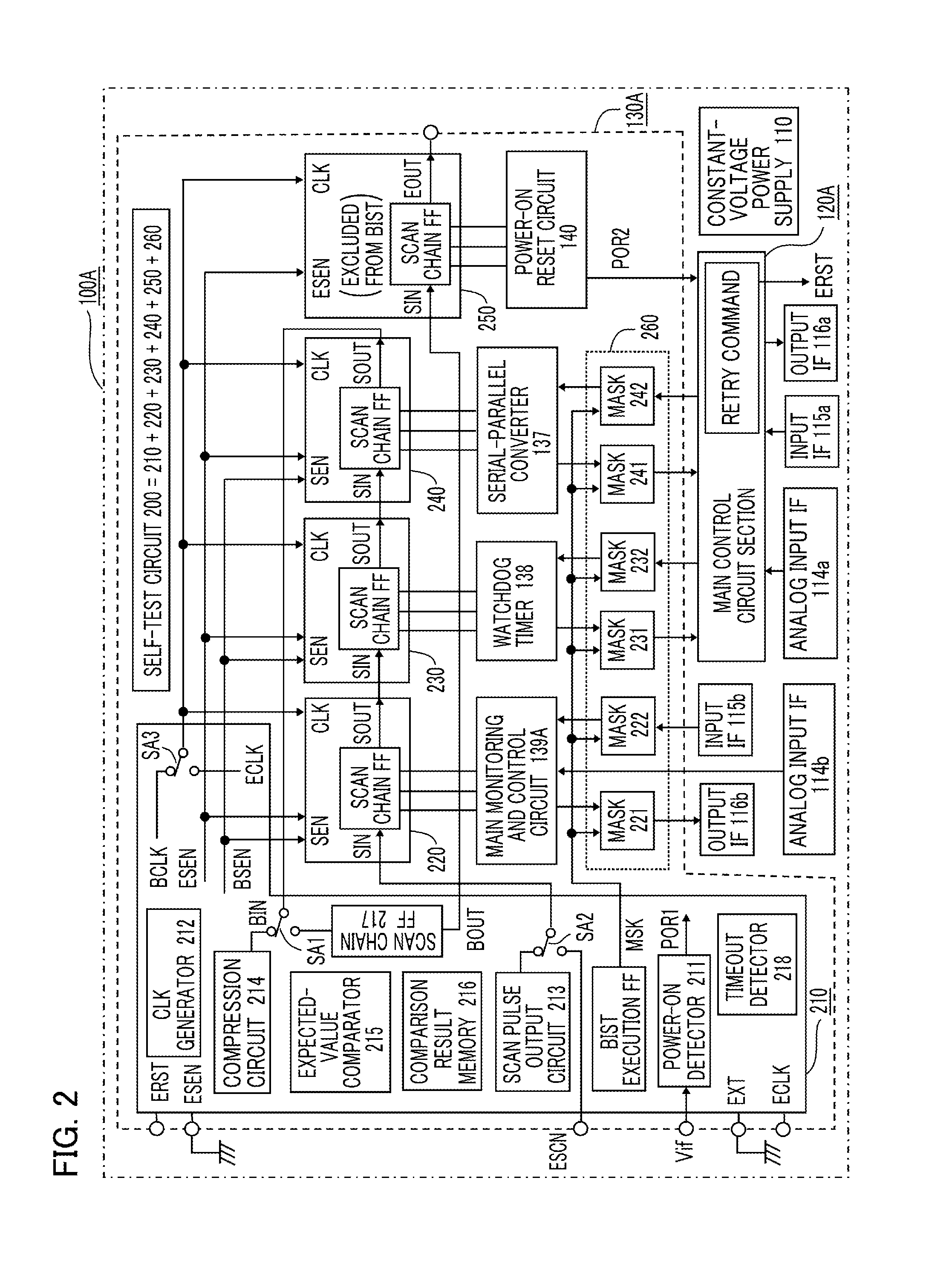
There is provided a low-cost electronic control unit that is capable of performing its hardware check every start and stop of the electronic control unit. A monitoring and control circuit section that is an integrated circuit element built in the electronic control unit includes a self-test circuit configured with a built-in self-test control block, scan chain circuits and mask circuitry, and performs a self-test using the built-in self-test control block and a partial combination of the scan chain circuits at start of the operation. In the shipment inspection of the integrated circuit element alone, an external test is performed by a checker microprocessor using an entire combination of the scan chain circuits. Thus, the electronic control unit of low-cost configuration is capable of performing a scan test by making use of part of the scan chain circuits designed for the component inspection.

Description

BACKGROUND OF THE INVENTION[0001]1. Technical Field[0002]The present invention relates to an electronic control unit that has an integrated circuit element and is mounted in, for example, a vehicle, and relates to a component test unit that performs in the product shipment stage a rationalized anomaly check associating mutually an anomaly check for the electronic control unit in actual operation with a component anomaly check for the integrated circuit element built in the electronic control unit.[0003]2. Description of the Related Art[0004]In an electronic control unit mounted in, for example, a vehicle that includes an input interface circuit connected to input sensors; an output interface circuit connected to electric loads; and at least one integrated circuit element connected with the input interface circuit and the output interface circuit, the electronic control unit performs during operation a check on connection states of wirings to the input sensors and the electric loads ...

Claims


Application Information

Patent Timeline
Patent Type & Authority Applications(United States)
IPC IPC(8): G01R31/3177
CPCG01R31/3177G01R31/318544G01R31/31724G01R31/318555
Inventor IWAGAMI, YUKITANAKA, SUSUMU
Owner MITSUBISHI ELECTRIC CORP
Learn More