Clothes dryer

Inactive Publication Date: 2014-12-18
SAMSUNG ELECTRONICS CO LTD
View PDF3 Cites 40 Cited by
  • Summary
  • Abstract
  • Description
  • Claims
  • Application Information

AI Technical Summary

Benefits of technology

[0079]Accordingly, the high temperature and high pressure state of the refrigerant can be prevented, and frost

Problems solved by technology

For this reason, a structure thereof may be complicated and manufacturing cost may be increased.
However, the filter clogging cannot be precisely detected due to many detection errors.
When the lint filter is imperfectly mounted, a gap may be generated and lint may intrude into the exhaust path.
Accordingly, when the above-mentioned anemometer is used in the clothes dryer, the lint may be caught by the rectification member to cause unstable measurement.
Accordingly, on all such occasions, the dryer should be disassembled and the anemometer should be taken out, thus requiring a complex operation.
Accordingly, the compressor temperature may deviate from an allowable use range and the compressor may overheat or stop.
However, in this case, a capacity of the heat pump is decreased and a drying time upon normal operation is also increased.
However, in order to efficiently radiate the heat to the outside of the heat exchange stove, an exclusive blower configured to blow air should be installed at the auxiliary condenser, which may cause an increase in size or cost of an apparatus.
In addition, while a method of cooling the auxiliary condenser using drained water may be employed to improve radiation efficiency, when the water cooling is performed, the heated drained water is evaporated, causing dew condensation in the housing or an increase in temperature and humidity therearound.
However, in such a conf

Method used


Image

  • Clothes dryer
  • Clothes dryer
  • Clothes dryer

Examples


first embodiment

(Configuration of Clothes Dryer)

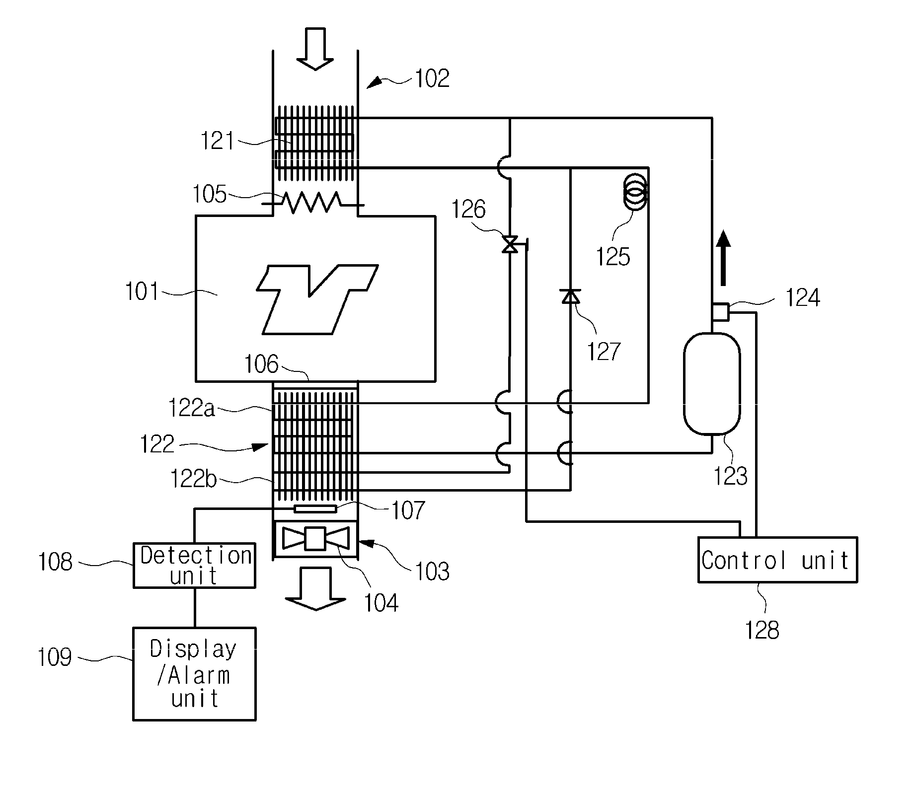
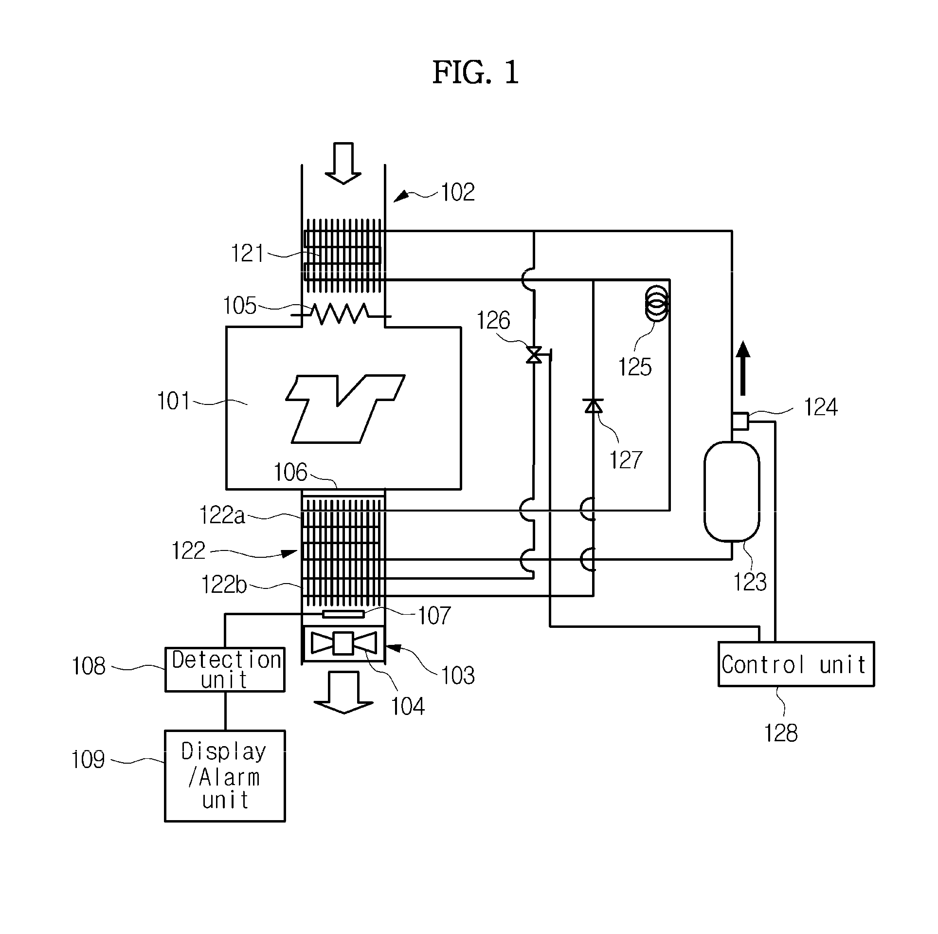
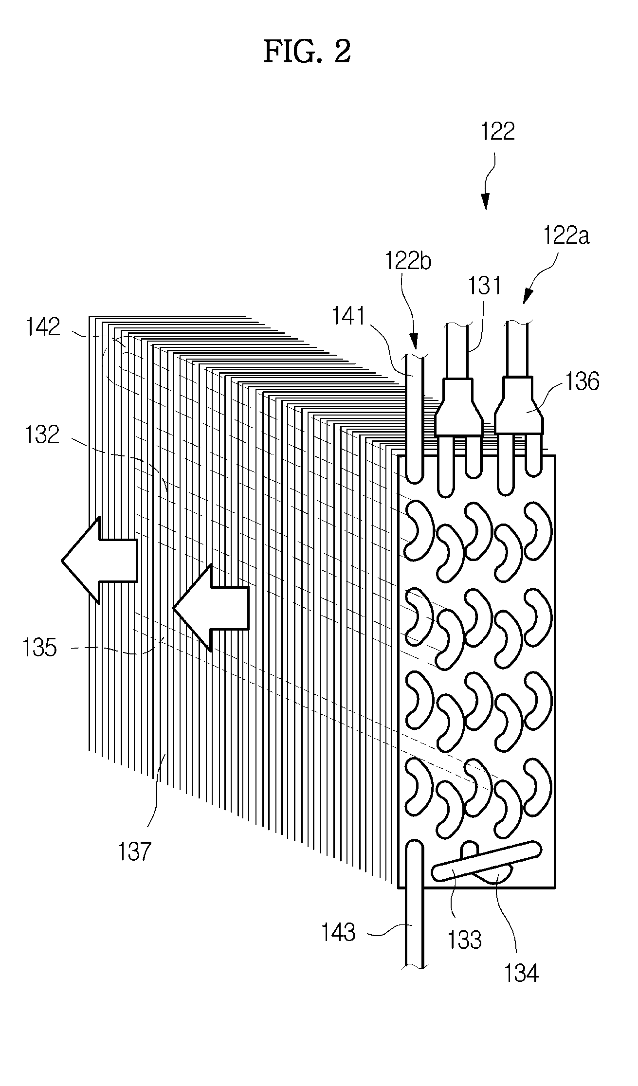
[0119]As shown in FIG. 1, a clothes dryer has, for example, a drying chamber 101 constituted by a rotary drum, a suction passage (an air passage) 102 and an exhaust passage (an air passage) 103, and air is flowed by a blower 104 to dry clothes in the drying chamber 101. A first condenser (a suction-side heat exchanger) 121 and a heater 105 of a heat pump are installed at the suction passage 102. In addition, a filter 106, an exhaust-side heat exchanger 122 and a flow velocity sensor 107 (to be described below) are installed at the exhaust passage 103. A display / alarm unit 109 is connected to the flow velocity sensor 107 through a detection unit 108. The exhaust-side heat exchanger 122 is constituted by an evaporator 122a and a second condenser 122b.

[0120]The heat pump is further constituted by a compressor 123, a refrigerant pressure sensor 124, a decompressor 125, a flow rate regulator 126, a check valve 127 and a control unit 128, in addition to th...

second embodiment

[0163]A clothes dryer 100 of a second embodiment is a suction / exhaust type, and as shown in FIG. 24, includes a drum 2 configured to accommodate clothes, a suction flow path 3 configured to suction air into the drum 2, an exhaust flow path 4 configured to exhaust the air from the drum 2, a heat pump circuit 5, and a control unit 6 configured to control the respective parts of the clothes dryer 100. In addition, a heater 7 configured to auxiliarily heat the suctioned air is installed at the suction flow path 3.

[0164]The heat pump circuit 5 has a main circuit 5a to which a compressor 53, a first condenser 54a, a decompressor 55 and an evaporator 56 are sequentially connected in a loop shape, and a sub-circuit 5b branched off between the compressor 53 and the first condenser 54a at the main circuit 5a, to which a refrigerant flow rate regulator 58, a second condenser 54b and a check valve 59 are sequentially connected, and joining the first condenser 54a and the decompressor 55. In add...

third embodiment

[0179]As shown in FIG. 27, in a clothes dryer of a third embodiment, the second condenser 54b is branched off between the first condenser 54a and the decompressor 55 of the main circuit 5a, the sub-circuit 5b joining the intersection and the decompressor 55 is provided, and a circuit switching device 60 configured to branch off the sub-circuit 5b from the main circuit 5a is installed at the intersection of the heat pump circuit 5. During normal operation, when a sub-circuit-side outlet of the circuit switching device 60 is closed and the refrigerant temperature or refrigerant pressure in the heat pump circuit 5 arrives at a predetermined level or more, the sub-circuit 5b side of the circuit switching device 60 is opened to decrease the refrigerant temperature and refrigerant pressure in the heat pump circuit 5. Another configuration is similar to the second embodiment, and detailed description is incorporated from the second embodiment. In addition, the same reference numerals desig...


PUM


Abstract

A clothes dryer configured to cause air to flow through a drying chamber, an exhaust passage (an air passage) 103 and a filter by a blower to dry clothes includes a heat pump installed in the exhaust passage (103) and having a heat exchanger (122) including a refrigerant pipe (132) and a pin, and a flow velocity sensor (107) of airflow having a hot thermistor (a heat generating body) 107a and a temperature compensation thermistor (a temperature detecting body) 107b and installed downstream from the heat exchanger (122), wherein the thermistors (107a and 107b) are disposed at a refrigerant pipe (132) of the heat exchanger (122) in parallel.

Description

CROSS-REFERENCE TO RELATED APPLICATION[0001]This application claims the benefit of Japanese Patent Application No. 2013-127658, filed on Jun. 18, 2013, Japanese Patent Application No. 2013-127674, filed on Jun. 18, 2013, Japanese Patent Application No. 2014-020639, filed on Feb. 5, 2014 in the Japanese Patent Office and Korean Patent Application No. 10-2014-0072519, filed on Jun. 16, 2014 in the Korean Intellectual Property Office, the disclosure of which is incorporated herein by reference.BACKGROUND[0002]1. Field[0003]Embodiments of the present invention relate to a clothes dryer having a heat pump.[0004]2. Description of the Related Art[0005]For example, in a rotary drum type clothes dryer, a filter is installed in an exhaust path for wet air discharged from clothes. In addition, a detection unit is configured to detect clogging of the filter and emit an alarm or the like when clogging is detected. For example, a differential pressure sensor configured to detect a pressure differ...

Claims


Application Information

Patent Timeline
IPC IPC(8): D06F58/20D06F58/02F26B21/00D06F58/28F26B23/00
CPCD06F58/206D06F58/28D06F58/02F26B21/004F26B23/001D06F34/26D06F58/50D06F2103/36D06F2103/50D06F2105/24D06F2105/26D06F2105/58D06F2105/60D06F2105/62
Inventor WAKIZAKA, EIJIAJIKI, TOMOHITOEIFUKU, YUJI
Owner SAMSUNG ELECTRONICS CO LTD
Why Eureka
Try Eureka