In-wheel motor and electrically driven vehicle

a technology of electric motors and motors, applied in mechanical devices, braking systems, transportation and packaging, etc., can solve the problems of complicated configuration, and restricting the space of the motor mechanism

Active Publication Date: 2014-12-18
CORELESS MOTOR CO LTD
View PDF3 Cites 13 Cited by
  • Summary
  • Abstract
  • Description
  • Claims
  • Application Information

AI Technical Summary

Benefits of technology

[0024]According to the second aspect of the present invention, it is possible to provide the electrically driven vehicle that achieves effects similar to those of the first aspect of the present invention.

Problems solved by technology

However, in Patent Document 1, since the brake disk is provided between the outer yoke and the wheel disk, space for the brake mechanisms (such as the brake disk and the caliper) are required inside the wheel disk in addition to the space for the motor mechanism; therefore, there is a problem that restriction is imposed on the space for the motor mechanism.
In Patent Document 2, a brake mechanism is provided on an inner circumferential side of an inner yoke, but a base of a brake disk support is fixed to a wheel disk via a hub, and a tip thereof is disposed on the inner yoke to fix the brake disk; therefore, there is a problem that the configuration is complicated.
Moreover, in Patent Document 2, the brake mechanism is disposed on the inner circumferential side of the motor mechanism inside the wheel disk, but the motor mechanism and the brake mechanism are separately configured; therefore, there is a problem that restriction is imposed on the space for the motor mechanism.
Furthermore, both Patent Documents 1 and 2 disclose a motor of a core type in which a coil is wound around an iron core; therefore, there is a problem that the weight is increased.

Method used


Image

  • In-wheel motor and electrically driven vehicle
  • In-wheel motor and electrically driven vehicle
  • In-wheel motor and electrically driven vehicle

Examples


first embodiment

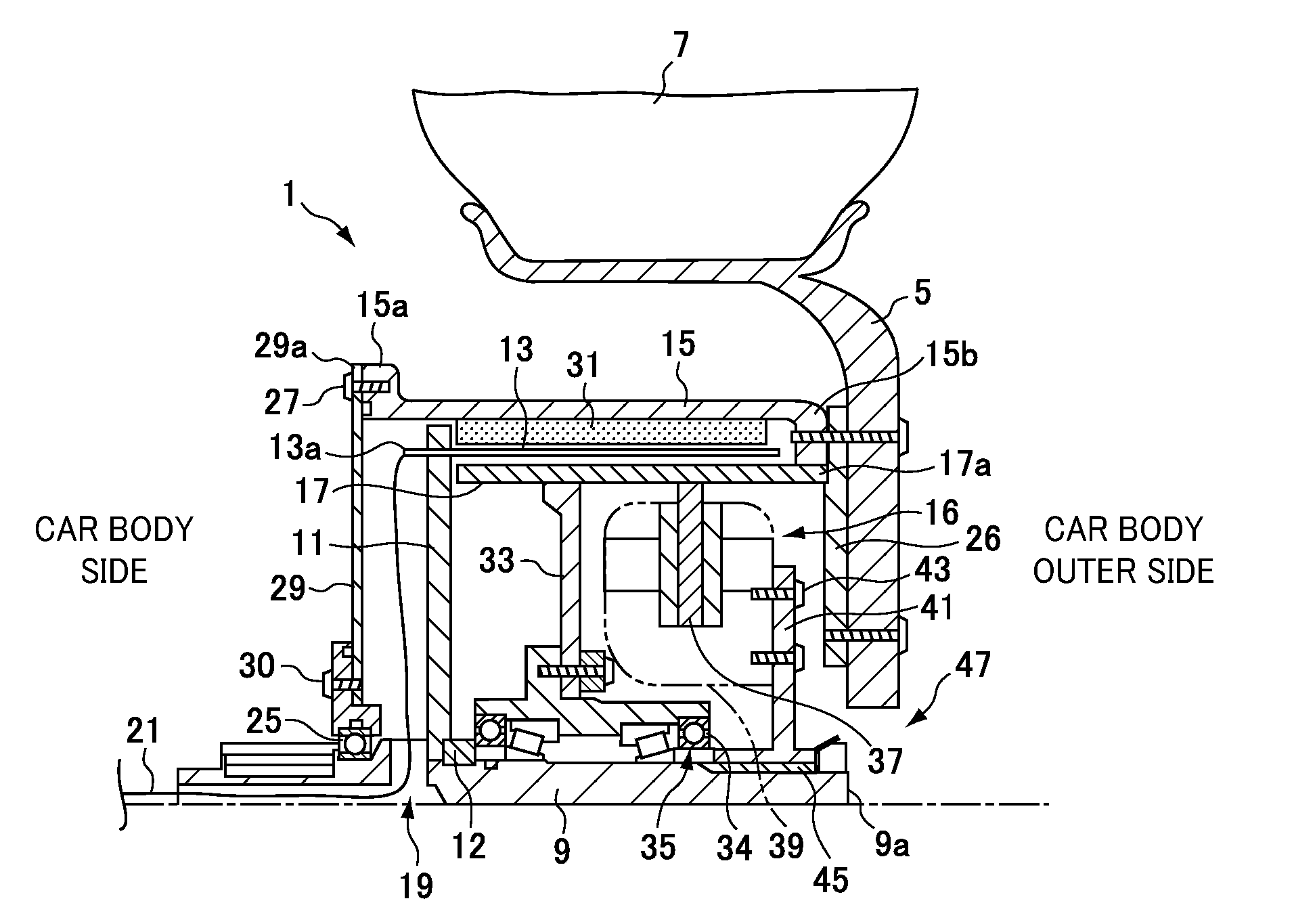
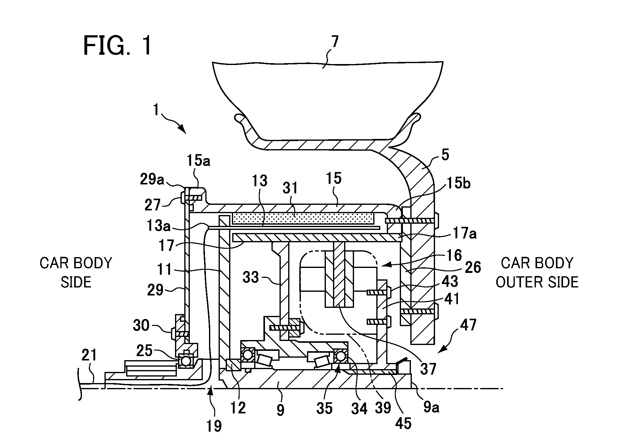
[0047]Since the in-wheel motor 1 is a motor of a so-called coreless type without an iron core, it is possible to provide an in-wheel motor that is more lightweight than a motor of a core type having an iron core such as those in the conventional art.

[0048]The inner yoke 17 and the outer yoke 15 are integrated, and the coil body 13 is disposed between the outer yoke 15, to which the magnet 31 is fixed, and the inner yoke 17; therefore, the outer yoke 15 and the inner yoke 17 can enhance the flux density of the magnet 31 acting on the coil body 13, and the driving torque can be enhanced.

[0049]The brake disk 37 is fixed to the inner yoke 17 that configures the motor mechanism of the in-wheel motor 1, and the brake disk 37 is disposed on the inner circumferential side of the inner yoke; therefore, the brake disk 37 can be disposed inside the inner yoke with a simple structure.

[0050]Since the brake disk 37 and the caliper 39 are disposed on the inner circumferential side of the coil bod...

second embodiment

[0056] when braking is applied to the wheel, the in-wheel motor 1 works as a generator to convert the rotational energy into electricity, and as a result, the in-wheel motor 1 can function as a regenerative brake.

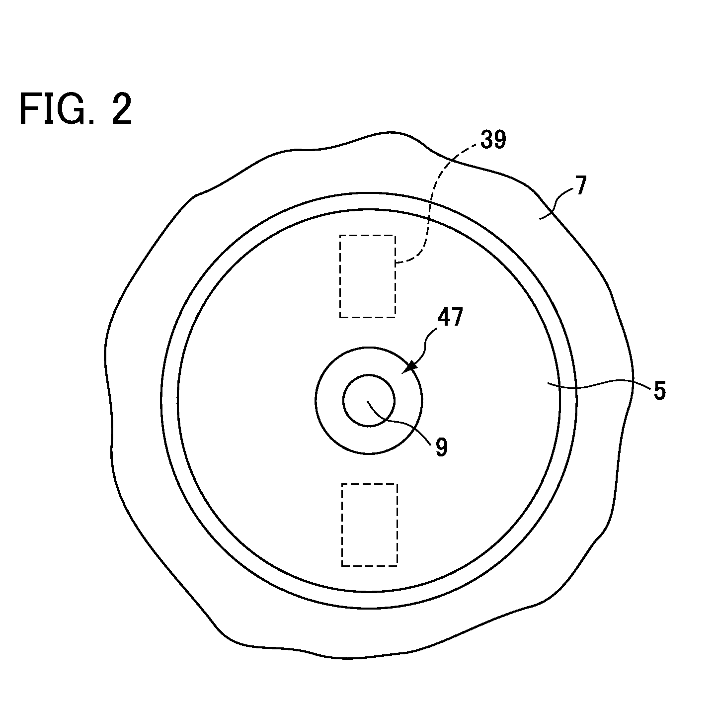
[0057]The present invention is not limited to the aforementioned embodiments, and can be modified in various ways without departing from the scope of the present invention. For example, in the first and second embodiments, the vent hole 47 of the wheel disk 5 may not be provided. Moreover, in a case in which the vent hole 47 is provided, the position thereof is not limited to the position facing the car body outer side edge 9a of the shaft 9, and the vent hole 47 may be provided in another position of the wheel disk 5, for example, a position spaced apart from the car body outer side edge 9a of the shaft 9.

[0058]Moreover, in the second embodiment, resistance may be connected to the driver 51 to convert the rotational energy into heat for generating heat.

third embodiment

[0059]the present invention is described with reference to FIG. 4. In the third embodiment, the magnet 31 fixed on the outer circumferential face of the inner yoke 17.

[0060]In the third embodiment an outer circumferential face of the magnet 31 may be wound with carbon fiber (not shown to prevent getting out by centrifugal force.

[0061]In the third embodiment, an inertial force of rotation is smaller than the first embodiment, therefore response of moving and stopping is better than the first embodiment. Also, in the third embodiment consumed energy is smaller than the first embodiment because of the inertial force of rotation is smaller than the first embodiment.


PUM


Abstract

The in-wheel motor for installation inside a wheel disk of a wheel includes: a cylindrical coil body; a coil body support member fixed to a shaft; an outer yoke that is disposed on an outer circumferential side of the coil body, and is fixed to a wheel disk; a cylindrical inner yoke that is disposed on an inner circumferential side of the coil body, and is rotatable around the shaft; and a magnet that is fixed on one of an inner circumferential face of the outer yoke and an outer circumferential face of the inner yoke, the magnet disposed to face a circumferential face of the coil body.

Description

[0001]This application is a continuation in part of application Ser. No. 13 / 174,583, filed Jun. 30, 2011, which is based on and claims the benefit of priority from Japanese Patent Application No. 2010-152109, filed on 2 Jul. 2010, the contents of which is incorporated herein by reference.BACKGROUND OF THE INVENTION[0002]1. Field of the Invention[0003]The present invention relates to an in-wheel motor that drives a wheel by a motor provided inside a wheel disk of the wheel, and particularly relates to an electrically driven vehicle such as an electric car, a hybrid car and a power-assisted bicycle.[0004]2. Related Art[0005]Patent Document 1 (Japanese Unexamined Patent Application, Publication No. H11-262101) discloses that an iron core and a coil wound around the iron core are provided on an inner circumferential face of an outer yoke (a motor container) that is fixed to a shaft, a magnet facing the iron core is rotatably provided to the shaft, and a current is applied to the coil, t...

Claims


Application Information

Patent Timeline
Patent Type & Authority Applications(United States)
IPC IPC(8): B60K7/00H02K7/102
CPCH02K7/102B60K7/0007B60K2007/0038B60K2007/0092B60T1/10B60T13/586F16D55/02F16D61/00F16D2055/005H02K7/14H02K21/22Y02T10/64
Inventor SHIRAKI, MANABUKITAJIMA, AKIRA
Owner CORELESS MOTOR CO LTD
Why Eureka
Try Eureka