Wind turbine blade with extended shell section

a wind turbine and shell technology, applied in the field of wind turbines, can solve the problems of increasing production costs, increasing the size of wind turbine blades today, and increasing the difficulty of designing effective blades, so as to improve the characteristics of blades

Inactive Publication Date: 2014-12-18
ENVISION ENERGY DENMARK
View PDF7 Cites 23 Cited by
  • Summary
  • Abstract
  • Description
  • Claims
  • Application Information

AI Technical Summary

Benefits of technology

[0017]An object of this invention is to provide a wind turbine blade with improved blade profile characteristics.

Problems solved by technology

The size of wind turbine blades today has also increased which in turn also increases the production costs as the design of an effective blade becomes more and more difficult.
The reduced trailing edge thickness is designed to reduce noise, but the limited width of the region will make it too stiff to significantly deform under loading, hence it should have a limited effect on the lift coefficient of the blade profile.
This adds to the complexity of the structure making it more fragile and susceptible to dirt, lightning damage and moisture.
Furthermore, such flaps or trailing edge require a separate active control system which in turn increase the production costs.

Method used


Image

  • Wind turbine blade with extended shell section
  • Wind turbine blade with extended shell section
  • Wind turbine blade with extended shell section

Examples


Embodiment Construction

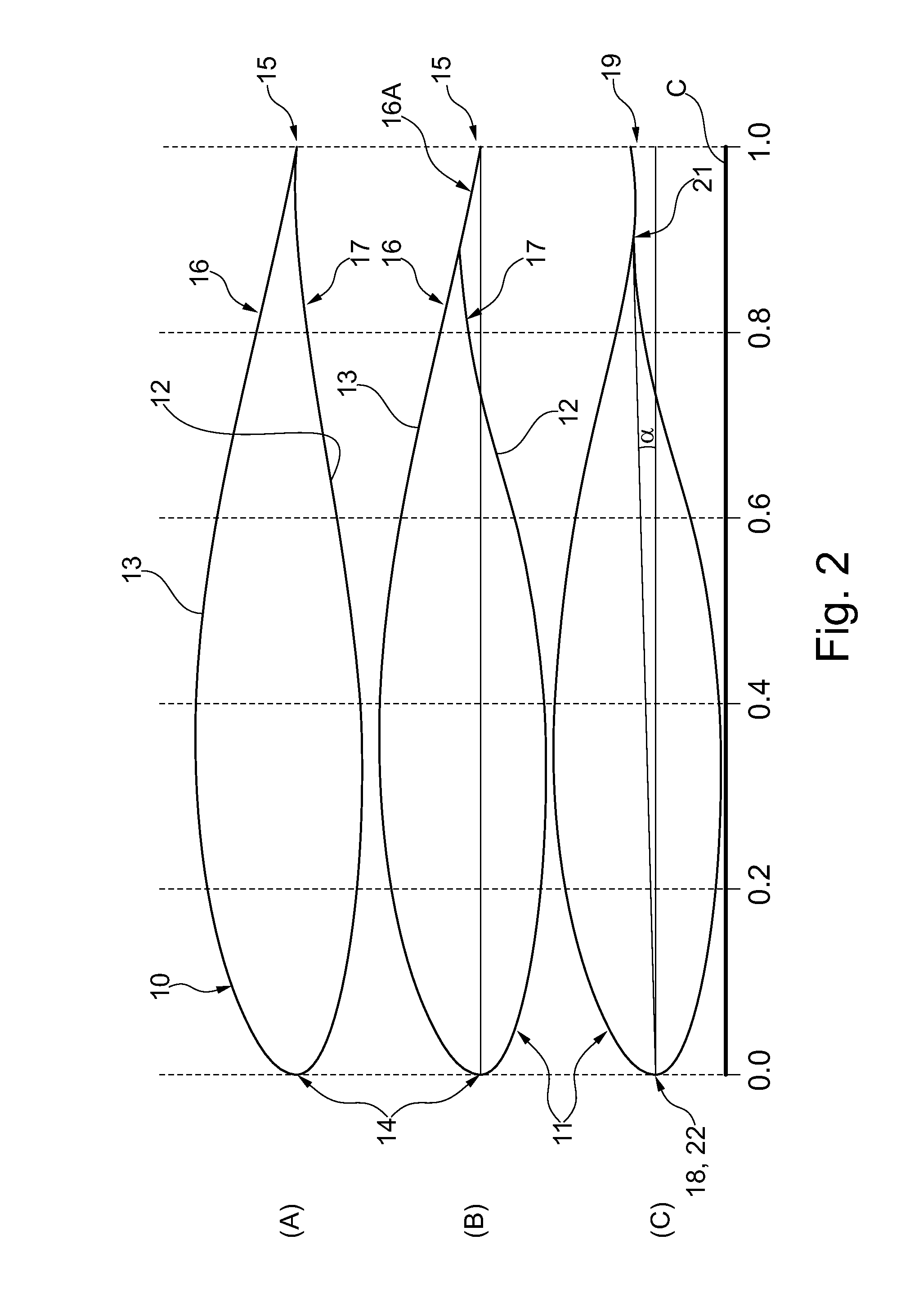
[0020]An object of the invention is achieved by a wind turbine characterised in that[0021]the extended shell section is configured as a flexible shell section for load reduction where the first trailing edge is configured to move from a first position to a second position in a direction towards the suction side relative to the first leading edge when an incoming wind is acting on the pressure side of the wind turbine blade, and[0022]wherein the chord of the wind turbine blade has a relative length of 1 and the extended shell section has a relative width of at least 0.10.

[0023]This provides a wind turbine blade with an improved blade profile where the extended shell section defines the trailing edge of the blade profile. The extended shell section allows the lift of the wind turbine blade to be optimised since it provides an extended trailing edge that is wider than the traditional trailing edge disclosed in US 2007 / 0098561 A1. The extended shell section has a configuration which ena...


PUM

PropertyMeasurementUnit
angular rotationaaaaaaaaaa
thicknessaaaaaaaaaa
thicknessaaaaaaaaaa

Abstract

The present invention relates to a manufacturing method for wind turbine blade and a wind turbine manufactured according to that method. The wind turbine blade comprises two shell parts wherein each shell part has a leading edge connected to a trailing edge via an inner surface. One of the two shell parts comprises an extended shell section which is configured as a flexible shell section. The shell section is configured to flex in a radial direction from a first position to a second position relative to the leading edge when an incoming wind is acting on the pressure side of the wind turbine blade. The wind turbine blade may be manufactured using a non-bonding layer removable arranged adjacent to the glue line between the two shell parts which reduces the amount of manual grinding or polishing of the glue region. This provides a wind turbine blade with an improved blade characteristic where the extended flexible shell section is specifically designed to have significant flexibility. The configuration provides a method for passively controlling the lift of the wind turbine blade.

Description

CROSS-REFERENCE TO RELATED APPLICATIONS[0001]This application claims the benefit of Dutch Application No. PA 2013 70323 filed Jun. 17, 2014, the contents of which are incorporated herein by reference.FIELD OF THE INVENTION[0002]The present invention relates to a wind turbine comprising:[0003]a wind turbine tower having a top;[0004]a nacelle coupled to the top of the wind turbine tower, e.g. via a yaw system;[0005]a rotor hub rotatably mounted to the nacelle;[0006]one or more wind turbine blades having a tip end located in the opposite end of a blade root configured to be mounted to the rotor hub, where the wind turbine blade comprises a pressure side connected to a suction side via a leading edge, wherein the wind turbine blade further comprises a first shell part having a first trailing edge connected to a first inner surface facing a second shell part, wherein the second shell part has a second trailing edge connected to a second inner surface facing the first shell part, wherein ...

Claims


Application Information

Patent Timeline
Patent Type & Authority Applications(United States)
IPC IPC(8): F01D5/14B29C65/48B29C70/48
CPCF01D5/141B29C65/48B29C70/48F05B2240/311F03D1/0675B29C65/483B29C66/1122B29C66/301B29C66/324B29C66/3242B29C66/3262B29C66/54B29C66/721B29C66/7212B29L2031/085F03D80/00Y02E10/72Y02P70/50B29K2307/04B29K2309/08F03D13/20
Inventor RUIJTER, WOUT
Owner ENVISION ENERGY DENMARK
Why Eureka
Try Eureka