Wiping device, ink-jet device, and wiping method

Inactive Publication Date: 2014-12-25
PANASONIC INTELLECTUAL PROPERTY MANAGEMENT CO LTD
View PDF2 Cites 6 Cited by
  • Summary
  • Abstract
  • Description
  • Claims
  • Application Information

AI Technical Summary

Benefits of technology

The invention allows for a stable gas flow parallel to the nozzle surface without touching it, and can easily remove any foreign particles or gaps on the edge of the nozzle.

Problems solved by technology

When such foreign matters adhere to the nozzle plate, appropriate discharging of ink is inhibited, and ink cannot be applied with high accuracy.
In wiping devices that use a gas flow to remove foreign matters, gas is applied also to the inner part of the nozzle hole when gas is obliquely applied to the nozzle plate, and consequently, the ink inside the nozzle hole is dried, causing nozzle clogging.
However, in a configuration in which gas is ejected or sucked in parallel to the nozzle plate at a location below the nozzle plate, the flow velocity of gas decreases as the distance from the nozzle plate decreases, and thus a gas flow that can stably blow away the foreign matters cannot be easily obtained.
However, such a configuration causes a problem in which the contact wears away the water-repellent film of the nozzle plate.

Method used


Image

  • Wiping device, ink-jet device, and wiping method
  • Wiping device, ink-jet device, and wiping method
  • Wiping device, ink-jet device, and wiping method

Examples


embodiment 1

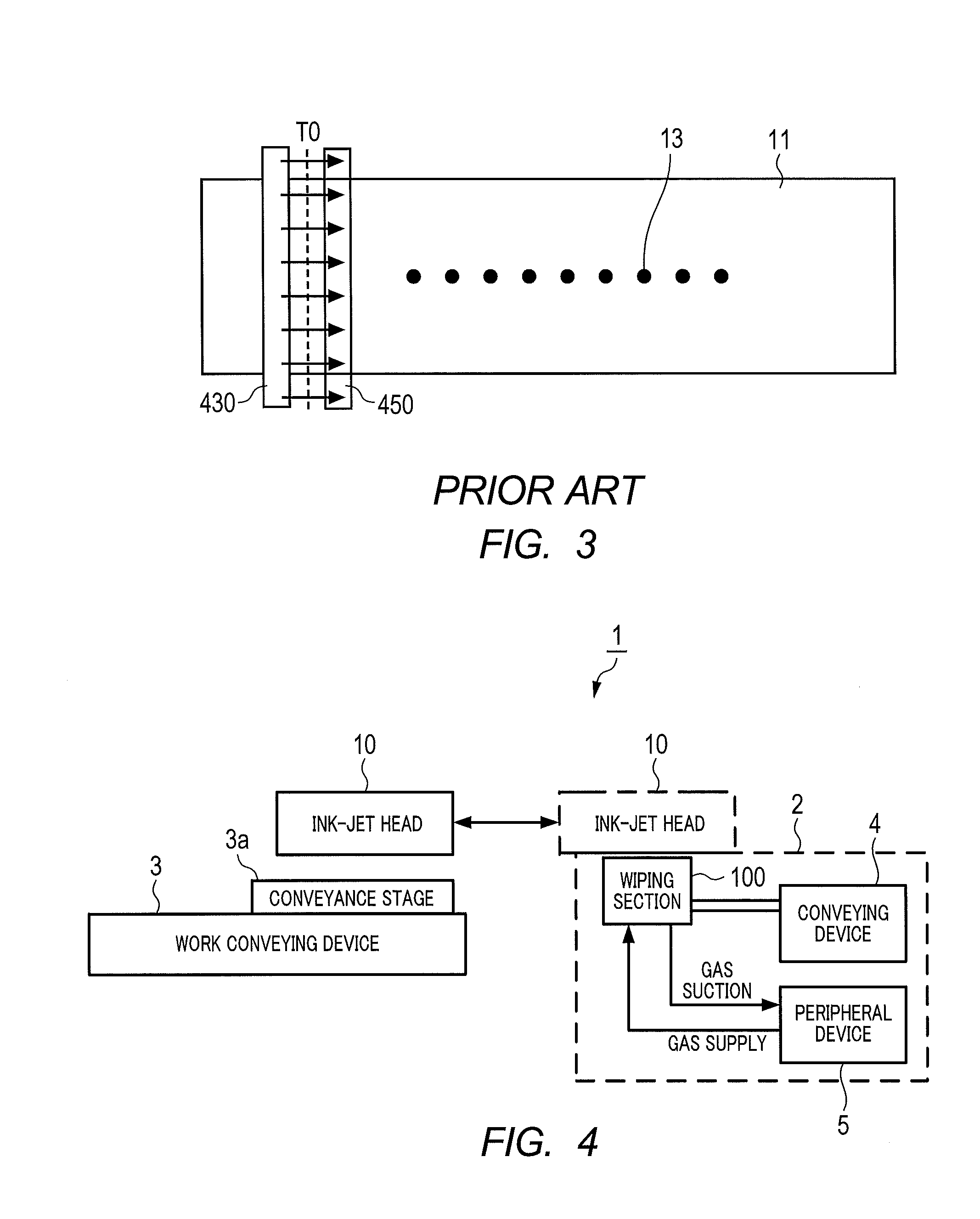
[0035]FIG. 4 is a block diagram illustrating an ink-jet device 1 of Embodiment 1 of the present invention.

[0036]Ink-jet device 1 of Embodiment 1 includes wiping device 2, ink-jet head 10, and work conveying device 3 that moves an object to be printed, which is placed on conveyance stage 3a and ink-jet head 10 relative to each other.

[0037]Wiping device 2 of Embodiment 1 includes wiping section 100, conveying device 4 that moves wiping section 100 relative to ink-jet head 10, and peripheral device 5 that supplies gas to wiping section 100 and sucks gas from wiping section 100.

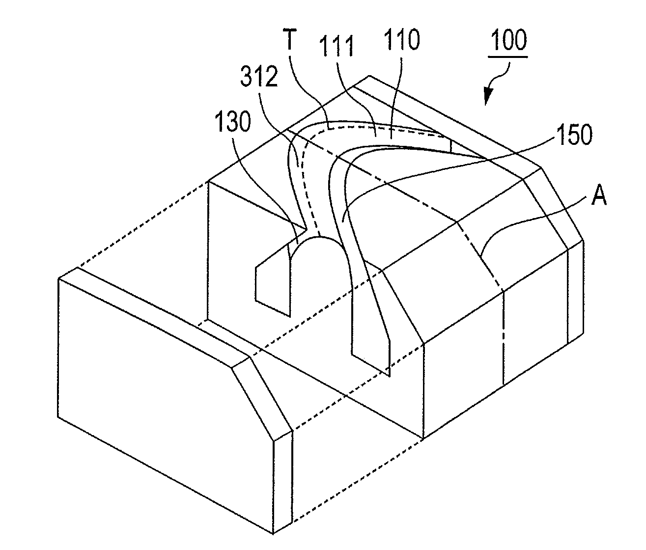
[0038]FIG. 5 is an exploded perspective view illustrating wiping section 100 of Embodiment 1 of the present invention. FIG. 6 is a schematic view illustrating a state where wiping section 100 of Embodiment 1 wipes ink-jet head 10. FIG. 6 illustrates a cross-section taken along dashed line A of FIG. 5. Dashed line A is a line that divides wiping section 100 perpendicularly to the nozzle surface, and divides wiping...

embodiment 2

[0092]FIG. 13 is a schematic view illustrating a cross-section of wiping section 200 of Embodiment 2. The components same as those of wiping section 100 of Embodiment 1 are denoted by the same reference symbols, and the description thereof is omitted.

[0093]As illustrated in FIG. 13, wiping section 200 of the present embodiment includes diffusion plate 501 disposed in gas jetting port 130 and diffusion plate 503 disposed in gas suction port 150. Each of diffusion plates 501 and 503 is provided so as to cover the entirety of a cross-section of the gas flow path.

[0094]Diffusion plates 501 and 503 have a large number of holes each having a diameter of 3 to 10 mm. The holes of diffusion plates 501 and 503 may either be uniformly or non-uniformly provided over diffusion plates 501 and 503.

[0095]To be more specific, the arrangement pitch of the holes at the center portion of diffusion plates 501 and 503 (the position near gas supply port 315, or gas exhaust port 317, for example) may be sm...


PUM


Abstract

A wiping device has a wiping section that relatively moves along the nozzle surface, and the wiping section has: a curved surface in which a bulge is continuously formed along the identification line; a guiding section disposed such that the bulge faces the nozzle surface; a gas jetting port that applies gas to the curved surface; and a gas suction port that sucks the gas ejected from the gas jetting port and guided along the curved surface, wherein, as viewed from the direction perpendicular to the nozzle surface, the identification line which is the set of upper end points on the bulge on the curved surface intersects with the edges of the nozzle surface at an oblique angle.

Description

CROSS REFERENCE TO RELATED APPLICATIONS[0001]The disclosure of Japanese Patent Application No. 2013-132977, filed on Jun. 25, 2013 and the disclosure of Japanese Patent Application No. 2014-047546, filed on Mar. 11, 2014 including the specification, drawings and abstract are incorporated herein by reference in their entirety.TECHNICAL FIELD[0002]The present invention relates to a wiping device of an ink-jet head, an ink-jet device, and a wiping method.BACKGROUND ART[0003]In recent years, in the manufacture of electronic devices, a method in which an application of ink containing a functional material is performed using an ink-jet head has been widely employed. The ink-jet head discharges ink to a printing target through minute nozzle holes provided in the nozzle plate.[0004]With such an ink-jet head, part of discharged ink or foreign matters such as dust in the outside air may adhere to the nozzle surface of the nozzle plate. When such foreign matters adhere to the nozzle plate, app...

Claims


Application Information

Patent Timeline
IPC IPC(8): F17D5/00
CPCF17D5/00Y10T137/87362Y10T137/0419B41J2002/16555B41J2/16552B41J2/16535
Inventor FUKADA, KAZUKIKIMURA, TEIICHI
Owner PANASONIC INTELLECTUAL PROPERTY MANAGEMENT CO LTD
Why Eureka
Try Eureka