Device for Detecting and/or Dosing Hydrogen and Method of Detecting and/or Dosing Hydrogen

a technology of detection and/or dosing device and hydrogen, which is applied in the direction of photometry using electric radiation detector, optical radiation measurement, instruments, etc., can solve the problems of limiting the detection and/or quantitative analysis of hydrogen, erroneous detection of hydrogen presence, and devices that present risks of bragg grating disappearance, etc., to achieve the effect of limiting the diffusion and reducing the diffusion of hydrogen

Active Publication Date: 2014-12-25
AGENCE NAT POUR LA GESTION DES DECHETAB RADIOACTIFS
View PDF1 Cites 7 Cited by
  • Summary
  • Abstract
  • Description
  • Claims
  • Application Information

AI Technical Summary

Benefits of technology

[0058]Partial permeability to hydrogen means that the coating is adapted to limit the penetration of hydrogen into the optical fibre that is equipped with said coating, without for all that completely eliminating the diffusion in said optical fibre.
[0059]Such a coating provides a means for limiting the diffusion of hydrogen in the second measuring optical fibre, with an influence on the optical properties of the second measuring optical fibre that is low, or even zero.

Problems solved by technology

Nevertheless, though such a device affords effective detection of the presence of hydrogen in the installation, it does have a certain number of drawbacks.
This is because such a device is dependent on the aging of the optical fibre which, if this state is not perfectly known, may cause erroneous detection of the presence of hydrogen.
This is because the optical fibre has a number of locations at which the detection and / or quantitative analysis is obtained that is limited since it is dependent on the inscription of a Bragg grating and the multiplexing technology used.
In addition such a device also presents risks of disappearance of the Bragg gratings because of the conditions of exposure of the optical fibre to hydrogen.

Method used


Image

  • Device for Detecting and/or Dosing Hydrogen and Method of Detecting and/or Dosing Hydrogen
  • Device for Detecting and/or Dosing Hydrogen and Method of Detecting and/or Dosing Hydrogen
  • Device for Detecting and/or Dosing Hydrogen and Method of Detecting and/or Dosing Hydrogen

Examples


first embodiment

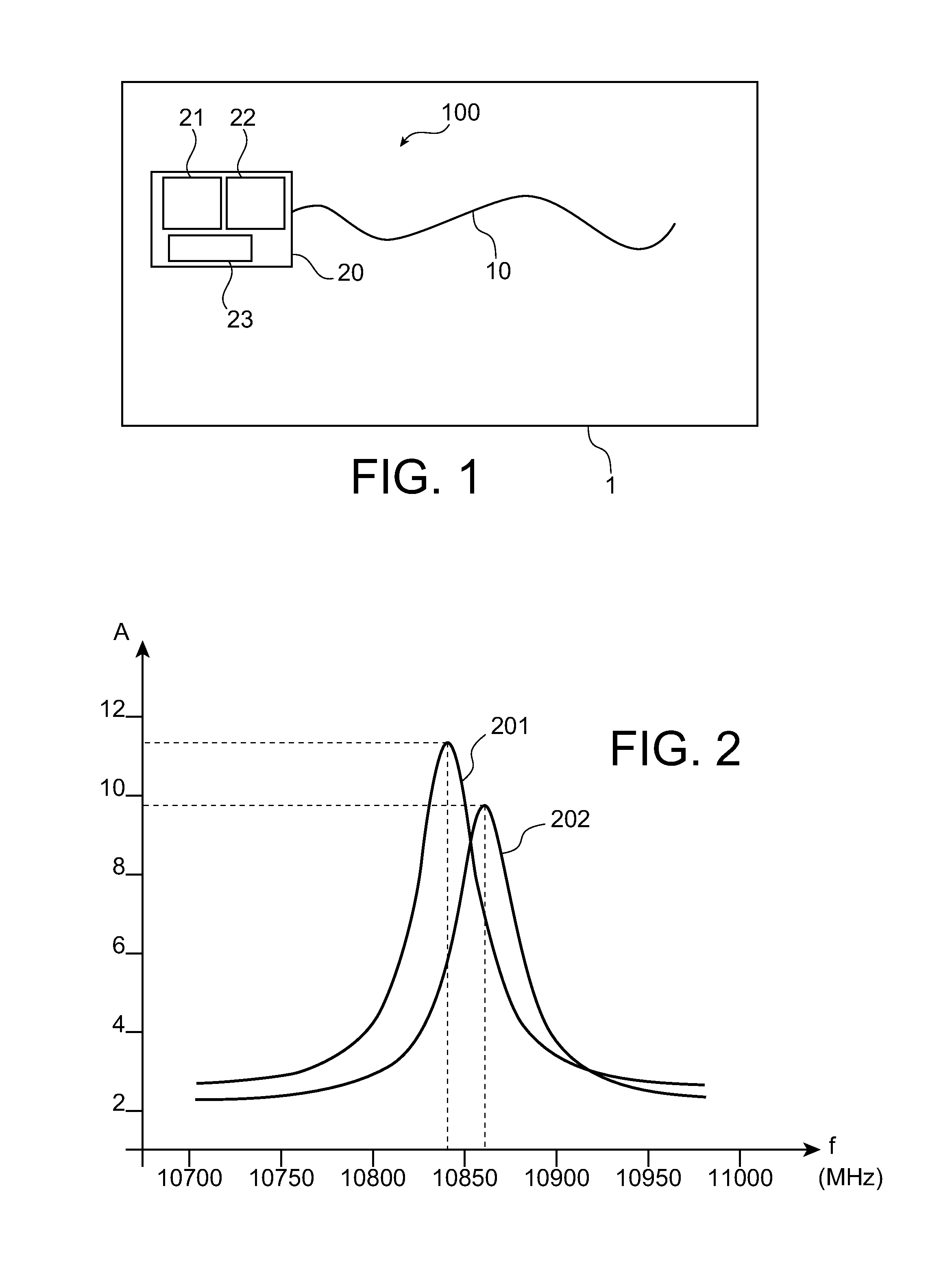
[0122]FIG. 2 illustrates an example of measurements made during the use of a device 100 according to this The Y axis represents the amplitude A of the intensity of the backscattered electromagnetic radiation in arbitrary units and the X axis represents the shift frequency f in the MHz of the backscattered radiation with respect to the radiation emitted by the emission means 21. During this use of the device 100, the first measuring optical fibre 10 has been put in the presence of a high hydrogen pressure (150 bar) for a period of 7 days so as to saturate the optical fibre with hydrogen. Then the first measuring optical fibre 10 has been returned to air for the same period so that the hydrogen degasses out of the first measuring optical fibre 10. The first spectrum 202 and the second spectrum 201, illustrated in this figure, were produced respectively at the end of the 7 days of exposure and at the end of the period of putting back in air.

[0123]Thus the first spectrum 202 shows a fr...

second embodiment

[0151]According to the first possibility of this second embodiment, the reference optical fibre 30 is an optical fibre configured so as to have reduced sensitivity to hydrogen. Such a configuration of the reference optical fibre 30 can be obtained either by a modified configuration of the fibre in itself, in accordance with the principle described in the document EP 1195628, or by the presence of a suitable coating on the surface of the reference optical fibre, such as the one described in the document EP 1426804.

[0152]The reference optical fibre 30 preferentially has, to facilitate the correction of the measurement of variation in effective propagation index of the optical mode neff along the first measuring optical fibre 10, characteristics similar to those of the first measuring optical fibre 10.

[0153]The first measuring optical fibre 10 and the reference optical fibre 30 are, when the installation is equipped with the device, installed side by side. To facilitate such equipping ...

third embodiment

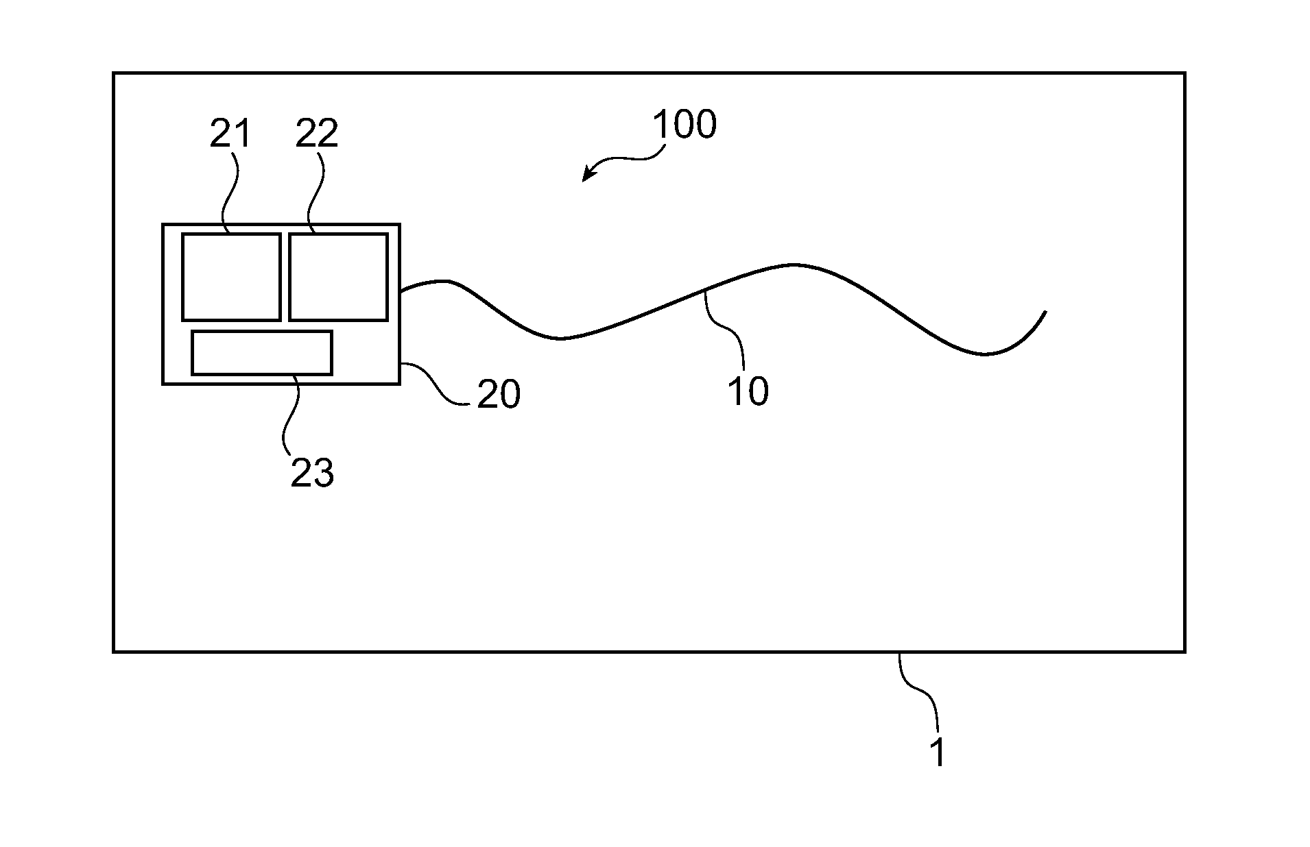
[0162]FIG. 11 illustrates a device in which the device comprises a second measuring fibre 11.

[0163]The device 100, as illustrated in FIG. 11, and in a similar manner to the first possibilities of the first and second embodiments, has a configuration suitable for making a Brillouin measurement according to the reflectometry principle.

[0164]A device according to the third embodiment is differentiated from a device according to the second embodiment in that it comprises a second measuring optical fibre 11 having an interaction with hydrogen different from that of the first measuring optical fibre 10. The optical system is furthermore adapted to make a measurement of a parameter according to the Brillouin measurement along the second measuring optical fibre 11, this parameter being identical to that measured along the first measuring optical fibre 10.

[0165]The second measuring optical fibre 11 has a different interaction to hydrogen that may be of various types.

[0166]A first type of in...


PUM

PropertyMeasurementUnit
wavelengthsaaaaaaaaaa

Abstract

The invention concerns a device (100) for the detection and/or quantitative analysis of hydrogen, intended for monitoring an installation (1). Said device (100) comprises a first measuring optical fibre (10) intended to equip the installation (1), and an optical system (20) optically connected to the first measuring optical fibre (10) and adapted to measure the variation in at least one parameter of the first measuring optical fibre (10). The optical system (20) is adapted to measure the parameter along the first optical fibre (10) according to the principle of Brillouin measurement. The invention also concerns a method using such a device (100).

Description

TECHNICAL FIELD[0001]The invention relates to the field of the detection and quantitative analysis of hydrogen.[0002]Installations such as storage premises, geothermal drillings, warehousing sites and industrial tanks of chemical and / or radioactive products may be subject to risks of release of hydrogen related to the products stored, these releases of hydrogen are explosive and may under certain conditions be harmful for humans.[0003]To control these risks and to preventatively detect any release of hydrogen that might take place, it is common to equip this type of storage premises with chemical detectors suitable for detecting and / or measuring hydrogen. Because of the long storage periods (several years) of chemical or radioactive products and the inaccessibility of the storage structures, the associated instrumentation and chemical detectors, such as hydrogen detectors, for obvious reasons of safety, must be durable over time, that is to say have optimum stability and sensitivity...

Claims


Application Information

Patent Timeline
Patent Type & Authority Applications(United States)
IPC IPC(8): G01N33/00G01N21/49G01N21/94
CPCG01N33/0057G01N21/94G01N21/49G01N2201/088G01N21/636G01N33/005G01N2021/638
Inventor BERTRAND, JOHANDELPHINE-LESOILLE, SYLVIEPHERON, XAVIER
Owner AGENCE NAT POUR LA GESTION DES DECHETAB RADIOACTIFS
Why Eureka
Try Eureka