Current sharing method for cot buck converter

a converter and current sharing technology, applied in the direction of electric variable regulation, process and machine control, instruments, etc., can solve the problems of complex control circuits of multi-phase converters and high implementation costs of single-phase counterparts

Active Publication Date: 2014-12-25
MICREL
View PDF9 Cites 45 Cited by
  • Summary
  • Abstract
  • Description
  • Claims
  • Application Information

AI Technical Summary

Problems solved by technology

Control circuits for multi-phase converters are generally more complex and costly in implementation than their single-phase counterparts.

Method used


Image

  • Current sharing method for cot buck converter
  • Current sharing method for cot buck converter
  • Current sharing method for cot buck converter

Examples


Embodiment Construction

[0013]The invention can be implemented in numerous ways, including as a process; an apparatus; a system; and / or a composition of matter. In this specification, these implementations, or any other form that the invention may take, may be referred to as techniques. In general, the order of the steps of disclosed processes may be altered within the scope of the invention.

[0014]A detailed description of one or more embodiments of the invention is provided below along with accompanying figures that illustrate the principles of the invention. The invention is described in connection with such embodiments, but the invention is not limited to any embodiment. The scope of the invention is limited only by the claims and the invention encompasses numerous alternatives, modifications and equivalents. Numerous specific details are set forth in the following description in order to provide a thorough understanding of the invention. These details are provided for the purpose of example and the inv...


PUM


Abstract

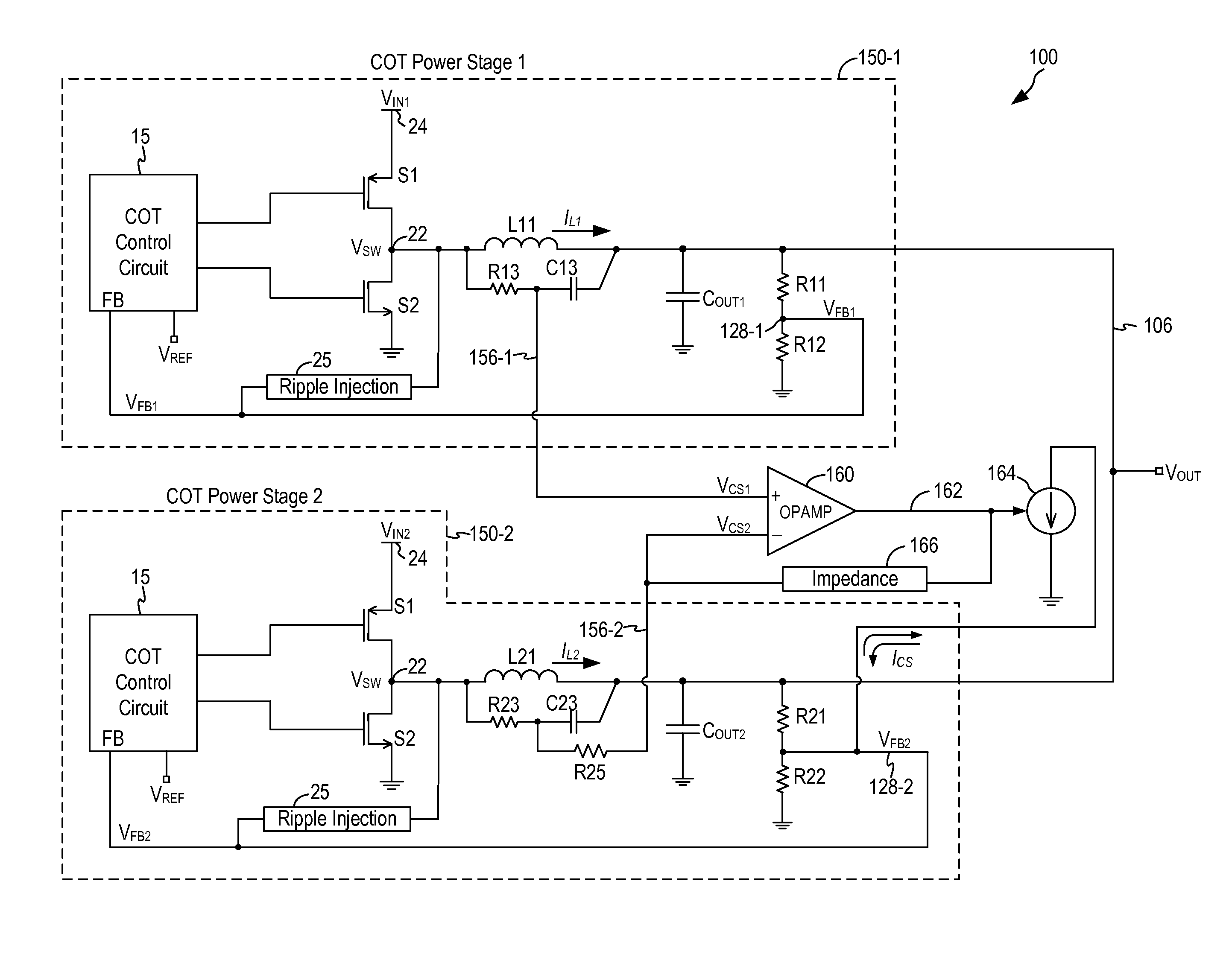
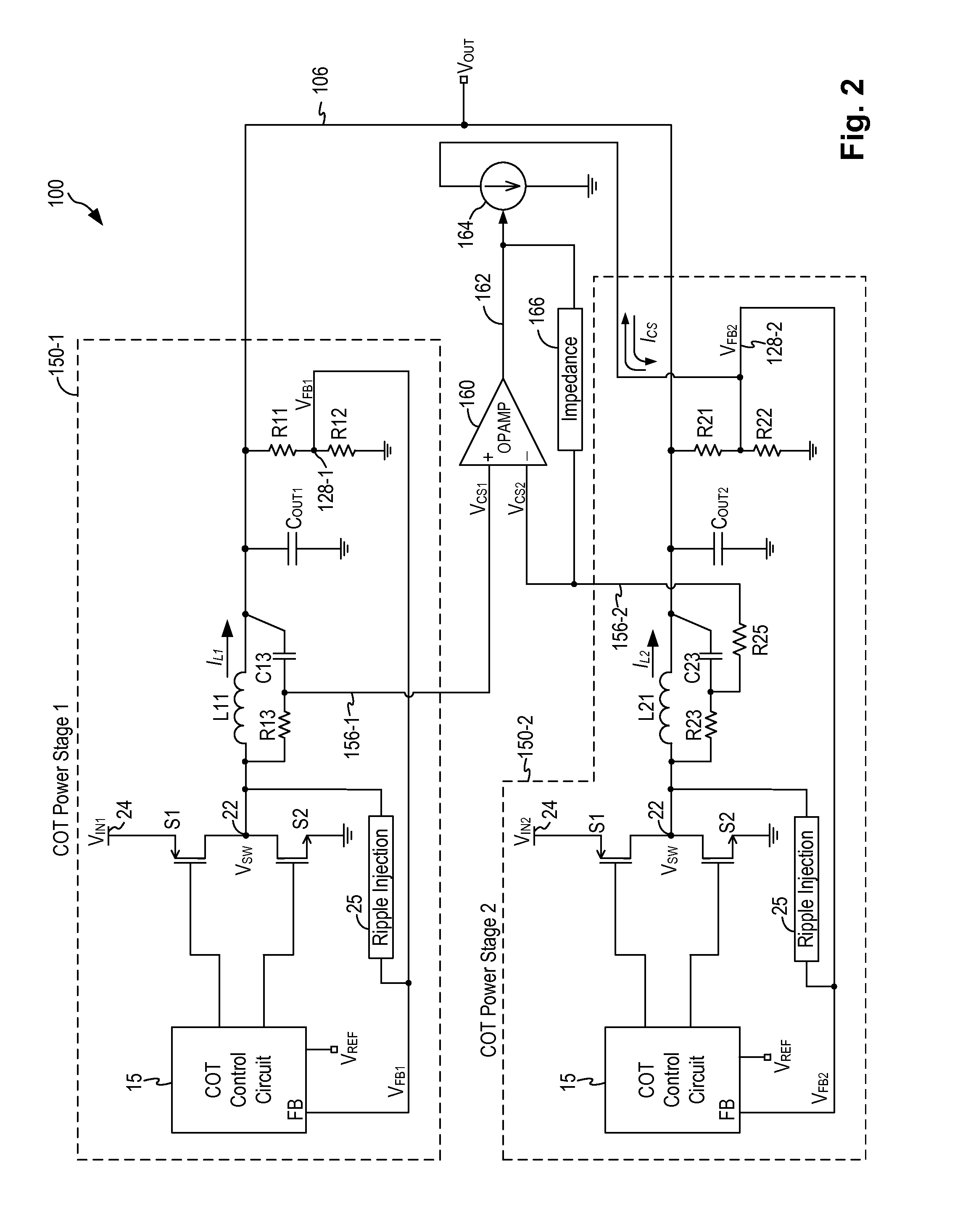
A power system for providing an output current at a regulated system output voltage includes a first power stage and a second power stage, each being a constant on-time (COT) controlled power converter. The first and second power stages generate respective first and second regulated output voltage having reduced or very small output ripple at a common output voltage node. The first and second power stages each includes a ripple injection circuit to inject a ripple signal to the feedback control circuit in each power stage. The power system further includes a current sharing control circuit configured to measure a first output current of the first power stage and a second output current of the second power stage, and to generate a control signal to modulate the feedback control circuit of the second power stage to force the second output current to equal to the first output current.

Description

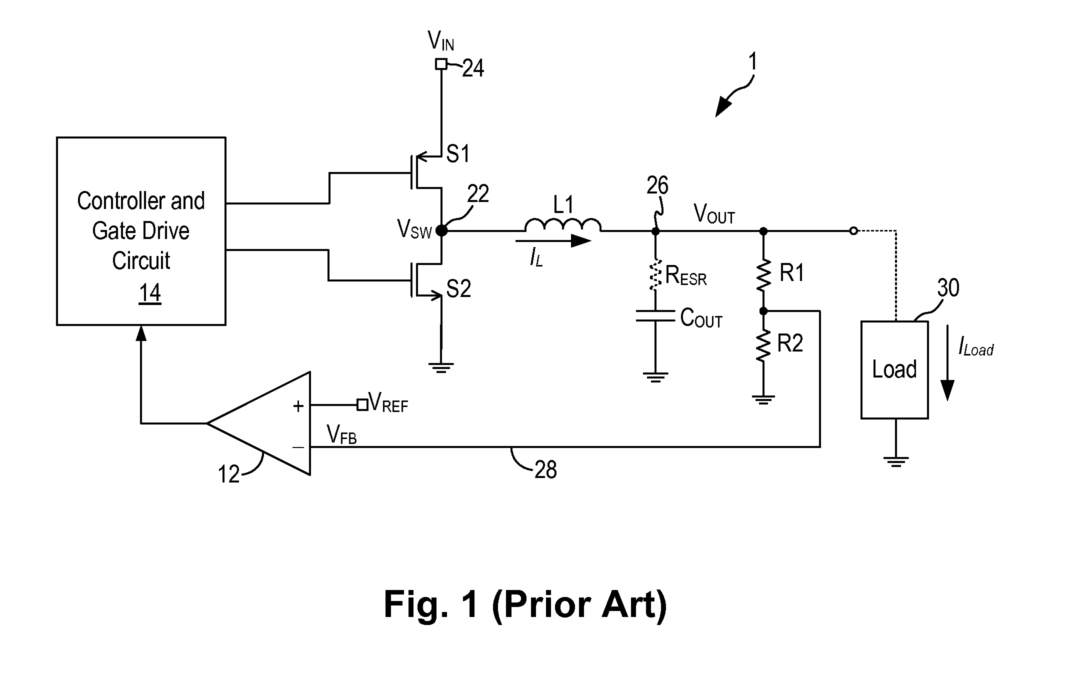
BACKGROUND OF THE INVENTION[0001]Switch mode power supplies or switching regulators, also referred to as DC to DC converters, are often used to convert an input supply voltage to an output voltage at a voltage level appropriate for the internal circuitry of an integrated circuit. For example, a 5 volts supply voltage provided to an integrated circuit may need to be reduced to 2.8 volts on the IC chip to operate the internal circuitry on the chip. A switching regulator provides power supply function through low loss components such as capacitors, inductors, and transformers, and power switches that are turned on and off to transfer energy from the input to the output in discrete packets. A feedback control circuit is used to regulate the energy transfer to maintain a constant output voltage within the desired load limits of the circuit.[0002]A switching regulator can be configured to step up the input voltage or step down the input voltage or both. Specifically, a buck switching regu...

Claims


Application Information

Patent Timeline
Patent Type & Authority Applications(United States)
IPC IPC(8): H02M3/158H02M1/00
CPCH02M3/1584H02M2003/1586H02M2003/1557H02M3/1557H02M3/1586H02J1/102H02J1/106H02M1/0009
Inventor NORA, PAOLO
Owner MICREL
Why Eureka
Try Eureka