Voltage controlled oscillator

a voltage control and oscillator technology, applied in oscillator generators, pulse automatic control, electrical equipment, etc., can solve the problems of reducing linearity, distortion of signals, and degradation of circuit performance, so as to achieve the effect of high gain and same power consumption

Inactive Publication Date: 2014-12-25
FOUND OF SOONGSIL UNIV IND COOP
View PDF2 Cites 3 Cited by
  • Summary
  • Abstract
  • Description
  • Claims
  • Application Information

AI Technical Summary

Benefits of technology

[0015]An aspect of the present invention provides a voltage controlled oscillator capable of having a high gain with the same power consumption.

Problems solved by technology

However, there is generally a limitation that the body of the transistor according to the related art is used to constantly maintain a threshold voltage.
An undesired change of the threshold voltage causes a distortion of a signal to reduce linearity.
In some cases, degradation in performance of a circuit such as an occurrence of a leakage current may be caused.
Since it is difficult to control the parameter of the manufacturing process and the physical parameter of the transistor, it is necessary to minimize influence of the parameters.
However, when a circuit is actually implemented, in order to maintain the threshold voltage, there is a limitation on performance.
In the related art to which a triple-well process is not applied, it is difficult to maintain the unique threshold voltage by connecting the source and the body.
For this reason, the bodies and the sources may be separated, and degradation in performance such as an increase of a Ron resistance may be caused due to a rise of the threshold voltage.
As another method, in order to prevent the threshold voltage from being increased, when the bodies are connected to the sources without sharing the substrate, a current flows through a resistance component of the substrate due to a voltage difference between the bodies, so that various problems such as heating, noise occurrence and signal leakage may be caused.

Method used


Image

  • Voltage controlled oscillator
  • Voltage controlled oscillator
  • Voltage controlled oscillator

Examples


Embodiment Construction

[0032]Exemplary embodiments of the present invention will now be described in detail with reference to the accompanying drawings.

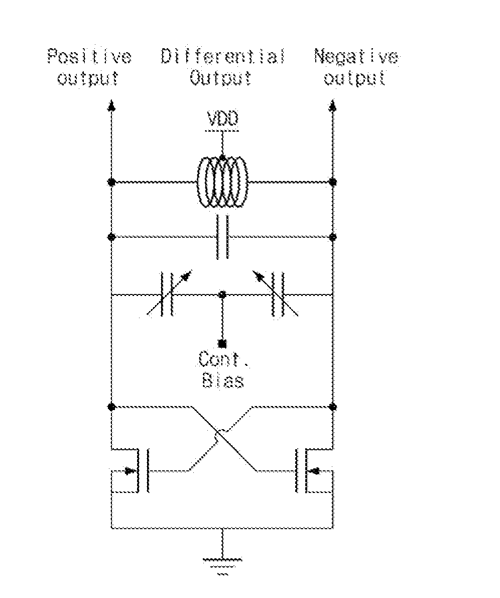
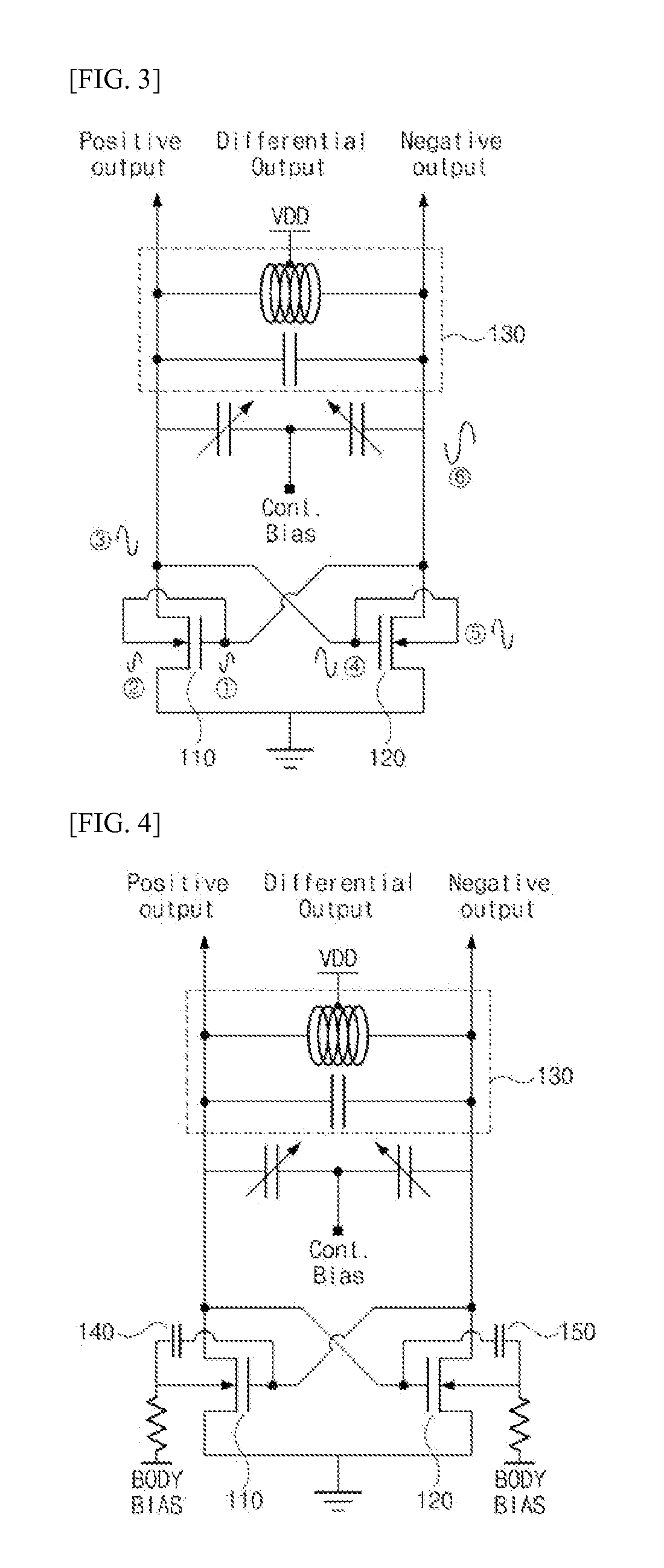
[0033]As set forth above, according to exemplary embodiments of the invention, since signals having the same phase as that of a gate and DC voltages are applied through bodies of transistors to adjust a threshold voltage, it is possible to obtain a relatively high gain with the same power consumption as compared to the related art, and since a feedback loop is additionally formed, it is possible to reduce an oscillating time.

[0034]Hereinafter, exemplary embodiments of the present invention will be described in detail with reference to the accompanying drawings to allow those skilled in the art to easily implement the exemplary embodiments. However, the present invention can be implemented in various manners, and is not limited to the exemplary embodiments. Parts that are not related to the description are omitted to clearly describe the present invention, ...


PUM


Abstract

Disclosed is a voltage controlled oscillator which includes a first transistor in which a first terminal is connected to a first power supply, a body is connected to a gate, and a first output signal is output through a second terminal; a second transistor that is cross-coupled to the first transistor in such a manner that a first terminal is connected to the first power supply, a body connected to the second terminal of the first transistor is connected to a gate, and a second terminal is connected to the body of the first transistor, and that outputs a second output signal having an opposite phase to that of the first output signal through the second terminal; and a resonance filter in which a first terminal is connected to the second terminal of the first transistor and a second terminal is connected to the second terminal of the second transistor.

Description

CROSS-REFERENCE TO RELATED APPLICATIONS[0001]This application claims the priority of Korean Patent Application No. 10-2013-0071645 filed on Jun. 21, 2013, in the Korean Intellectual Property Office, the disclosure of which is incorporated herein by reference.BACKGROUND OF THE INVENTION[0002]1. Field of the Invention[0003]The present invention relates to a voltage controlled oscillator, and more particularly, to a voltage controlled oscillator capable of obtaining a relatively high gain value with the same power consumption by controlling a body effect of a power amplifier of the voltage controlled oscillator.[0004]2. Description of the Related Art[0005]In general, a voltage controlled oscillator is a device that allows a desired oscillation frequency to be output by using a voltage applied from the outside. A voltage controlled oscillator that uses transistors which are cross-coupled to each other is disclosed as a related technology.[0006]FIG. 1 illustrates a cross-coupled LC volta...

Claims


Application Information

Patent Timeline
Patent Type & Authority Applications(United States)
IPC IPC(8): H03B5/02H03B5/12
CPCH03B5/1228H03B5/02H03B5/1212H03B2200/0062H03B5/124H03B5/12
Inventor PARK, CHANG KUNCHO, SEONG WOONGYOON, JAE HYUKLEE, MI LIM
Owner FOUND OF SOONGSIL UNIV IND COOP
Why Eureka
Try Eureka