Phosphor device and illumination system and projection apparatus with the same

a technology of phosphor and phosphor agent, which is applied in the direction of fixed installation, lighting and heating apparatus, instruments, etc., can solve the problems of insufficient total amount of red light converted from red phosphor agent, insufficient luminance and brightness of red light, and impaired image quality, etc., to achieve high manufacturing cost, large product volume, and complex fabrication process

Active Publication Date: 2014-12-25
DELTA ELECTRONICS INC
View PDF1 Cites 0 Cited by
  • Summary
  • Abstract
  • Description
  • Claims
  • Application Information

AI Technical Summary

Benefits of technology

[0010]It is an object of the present invention to provide an illumination system and a projection apparatus for obviating the drawbacks of high fabricating cost, complex fabricating process, large product volume, low luminance and brightness, insufficient color purity and impaired imaging quality encountered from a conventional illumination system of the projector.
[0011]The present invention provides an illumination system and a projection apparatus with a single phosphor device in order to reduce the fabricating cost, simplify the fabricating process, reduce the overall product volume, increase the overall luminance, increase the color purity and enhance the imaging quality.
[0012]The present invention also provides an illumination system and a projection apparatus with a single phosphor device. By the phosphor device, a first waveband light is converted into a third waveband light with a wider waveband. As the driving current of the blue solid-state light-emitting element increases, the possibility of attenuating the red light will be reduced. Consequently, the overall luminance and brightness will be increased, and the color performance is enhanced.

Problems solved by technology

That is, the color purity is insufficient, and thus the imaging quality is impaired.
Moreover, the exciting efficiency of red phosphor is lower and easier saturated than the green phosphor, the total amount of red light converted from the red phosphor agent is insufficient.
Under this circumstance, the luminance and brightness of the red light is too low, and the bright / dark status of the illumination system fails to be effectively controlled.
Consequently, the overall amount of the output light is limited.

Method used


Image

  • Phosphor device and illumination system and projection apparatus with the same
  • Phosphor device and illumination system and projection apparatus with the same
  • Phosphor device and illumination system and projection apparatus with the same

Examples


Embodiment Construction

[0034]The present invention will now be described more specifically with reference to the following embodiments. It is to be noted that the following descriptions of preferred embodiments of this invention are presented herein for purpose of illustration and description only. It is not intended to be exhaustive or to be limited to the precise form disclosed.

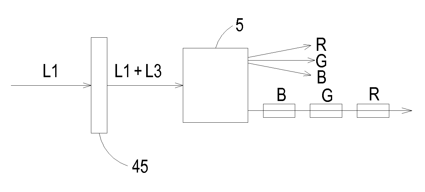
[0035]FIG. 3 schematically illustrates the concept of a projection apparatus with a phosphor device according to an embodiment of the present invention. As shown in FIG. 3, the phosphor device 40 is used in an illuminating system that emits a first waveband light L1 and has an optical path P. The phosphor device 40 comprises a first section 401 and a first phosphor agent 402 (see FIG. 6A). The first section 401 is coated with the first phosphor agent 402. After the first waveband light L1 from the illuminating system is received by the first phosphor agent 402, the first waveband light L1 is converted into a third waveband light ...


PUM


Abstract

A phosphor device of an illumination system is provided. The illumination system emits a first waveband light and has an optical path. The phosphor device includes a first section and a first phosphor agent. The first phosphor agent is coated on the first section. After the first waveband light is received by the first phosphor agent, the first waveband light is converted into a third waveband light, and the third waveband light is directed to the optical path, so that the third waveband light is separated into at least two color lights along the optical path.

Description

CROSS-REFERENCE TO RELATED APPLICATION[0001]This application is a Continuation Application of U.S. patent application Ser. No. 13 / 617,201 filed on Sep. 14, 2012, and entitled “PHOSPHOR DEVICE AND ILLUMINATION SYSTEM AND PROJECTION APPARATUS WITH THE SAME”, which claims the benefit of U.S. Provisional Application No. 61 / 537,687 filed on Sep. 22, 2011, and entitled “HYBRID SOLID STATE ILLUMINATION IN PROJECTORS”, the entirety of which is hereby incorporated by reference.FIELD OF THE INVENTION[0002]The present invention relates to a phosphor device, and more particularly to a phosphor device containing a single phosphor agent. The present invention also relates to an illumination system and a projection apparatus with the phosphor device in order to produce three primary color lights.BACKGROUND OF THE INVENTION[0003]In recent years, a variety of projectors have been widely used in various video applications. For example, projectors can be used for making presentations, holding meetings...

Claims


Application Information

Patent Timeline
Patent Type & Authority Applications(United States)
IPC IPC(8): G03B21/20H04N9/31F21K99/00F21V13/08F21V9/16F21V9/08F21V9/40G02B7/00
CPCG03B21/204F21V9/16F21V9/08H04N9/3158F21V13/08H04N9/3164F21K9/56G02B27/1006G02B7/00G03B21/00H04N9/3114F21V9/30H04N9/3105B05D5/06B32B2307/422
Inventor WANG, BORCHANG, KEH-SUHUA, CHIEN-HAO
Owner DELTA ELECTRONICS INC
Why Eureka
Try Eureka