Interferometer

a technology of interferometer and polarization beam, which is applied in the direction of measuring devices, instruments, using optical means, etc., can solve the problems that the polarization beam-splitting cube and the triple prism can only be produced with great expense, and the mounting of these components is costly and low-drift. to achieve the effect of simple manufacturing

Active Publication Date: 2014-12-25
DR JOHANNES HEIDENHAIN GMBH
View PDF3 Cites 4 Cited by
  • Summary
  • Abstract
  • Description
  • Claims
  • Application Information

AI Technical Summary

Benefits of technology

[0006]Example embodiments of the present invention provide a compactly constructed interferometer having optical components that are simple to manufacture.

Problems solved by technology

It is disadvantageous with regard to such interferometers that both the polarization beam-splitter cube and the triple prism can only be produced with great expense.
In the case of the spatially separate placement of beam-splitter cube and triple prisms, a very costly low-drift mounting of these components is likewise necessary.

Method used


Image

  • Interferometer
  • Interferometer
  • Interferometer

Examples


Embodiment Construction

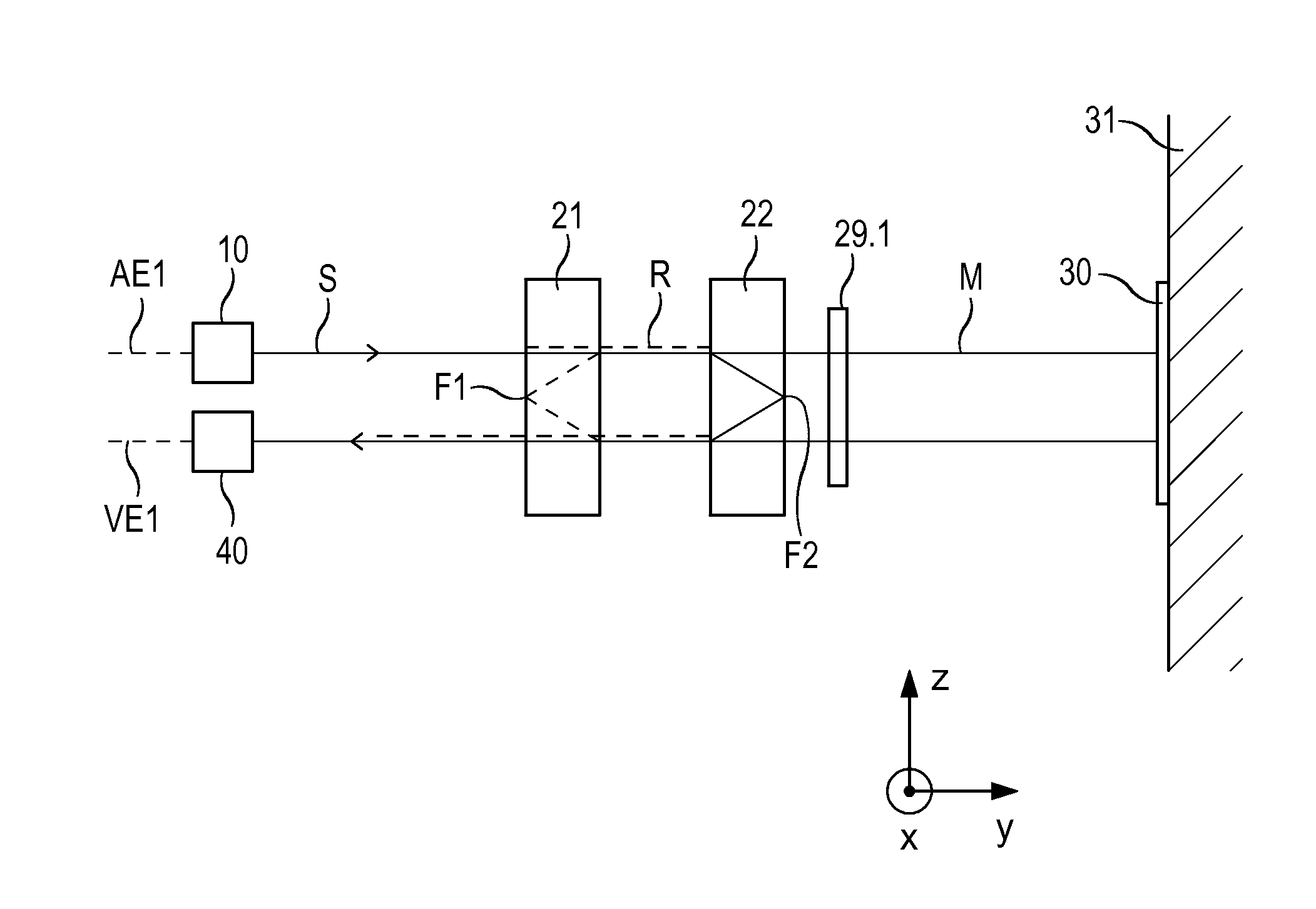
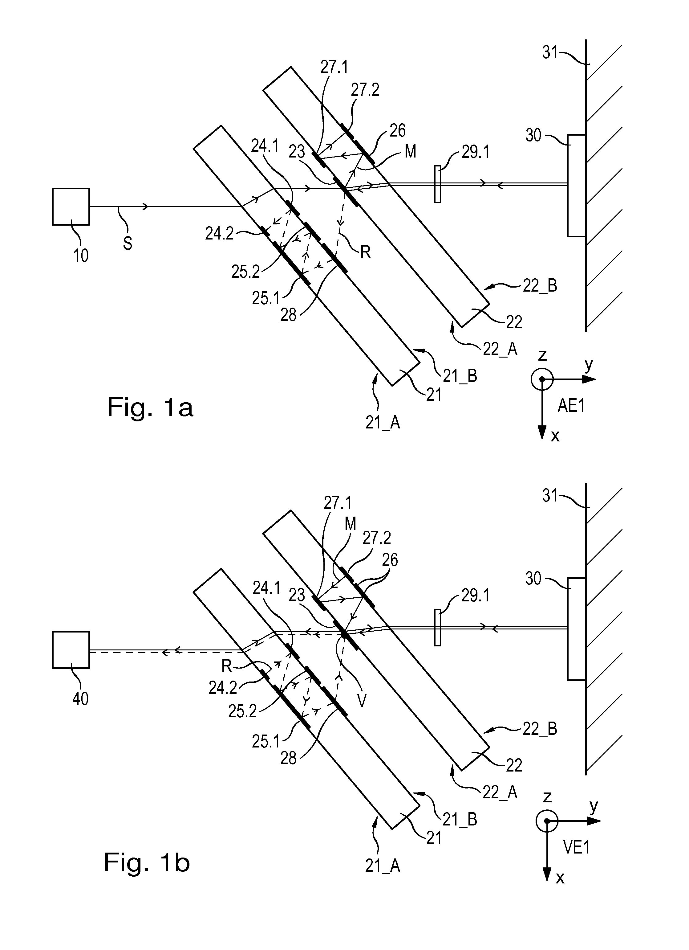
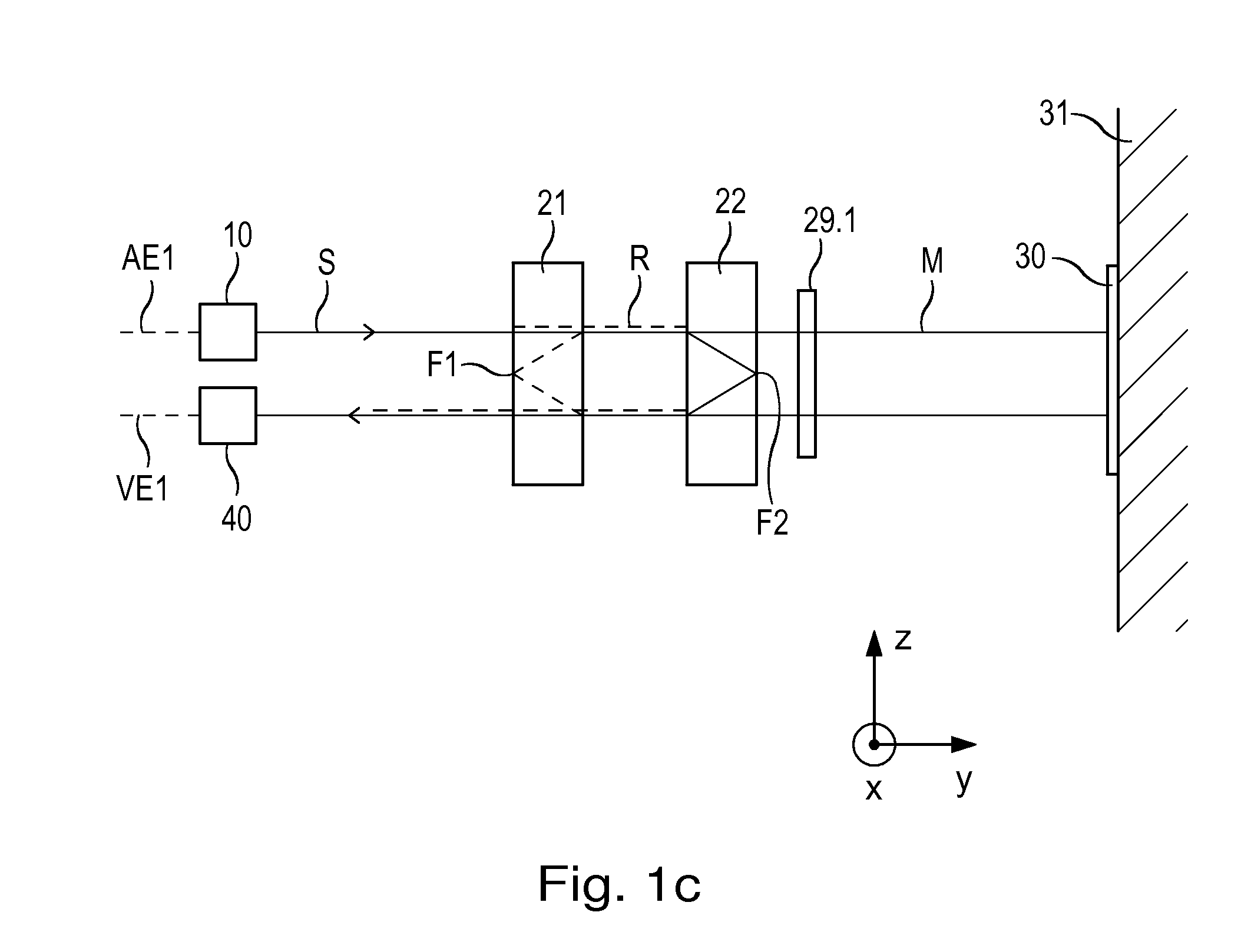
[0034]An interferometer according to a first example embodiment of the present invention is described below with reference to FIGS. 1a to 1c, 2a to 2d, 3, and 4a to 4c. FIGS. 1a to 1c show the beam path in different views, and FIGS. 2a to 2d are plan views of various interferometer components from the viewing direction of the measuring reflector. FIGS. 3 and 4a to 4c represent only an alternative simplified depiction of the first exemplary embodiment, which will be discussed subsequent to the specific description of the beam path.

[0035]The interferometer includes at least one light source 10, a beam splitter 23, a measuring reflector 30, a reference retroreflector, a detector system 40, and two transparent plane plates 21, 22. The two plane plates 21, 22, formed of a suitable glass material, for example, are placed parallel to each other in the beam path between light source 10 and detector system 40. As illustrated in FIGS. 1a and 1b, the two plane plates 21, 22 are arranged to be ...


PUM


Abstract

An interferometer includes a light source, a beam splitter, a measuring reflector, a reference retroreflector, a detector system, and two transparent plane plates. The beam splitter splits a first beam of rays, emitted by the light source, into at least one measuring beam and at least one reference beam, via which a first splitting plane is defined. The measuring beam propagates in a measuring arm and the reference beam propagates in a reference arm until being recombined at a recombining location in a first recombining plane. The first recombining plane is oriented parallel to the first splitting plane. The measuring reflector, on which the measuring beam falls perpendicularly at least twice, is disposed in the measuring arm and is joined to an object to be measured that is movable along a measuring direction. The reference retroreflector, on which the reference beam falls at least once, is disposed in the reference arm. At least one first distance signal with regard to the position of the object to be measured is ascertainable via the detector system from the interfering measuring and reference beams superposed at the recombining location. The first transparent plane plate and the second transparent plane plate are disposed parallel to each other in the beam path between the light source and the detector system. The reference retroreflector is formed in the first plane plate and the beam splitter is disposed on the second plane plate.

Description

CROSS-REFERENCE TO RELATED APPLICATIONS[0001]The present application claims priority to Application No. 10 2013 211 758.2, filed in the Federal Republic of Germany on Jun. 21, 2013, which is expressly incorporated herein in its entirety by reference thereto.FIELD OF THE INVENTION[0002]The present invention relates to an interferometer, e.g., that is particularly suitable for the high-precision measurement of length and / or distance.BACKGROUND INFORMATION[0003]A plane-mirror interferometer is described in U.S. Pat. No. 4,752,133 and includes a light source, a beam splitter, and a detector system. A beam of rays emitted by the light source is split via the beam splitter into at least one measuring beam and at least one reference beam. The measuring beam and the reference beam then propagate in a measuring arm and in a reference arm, respectively, until they are recombined at the beam splitter. In the measuring arm, a measuring reflector in the form of a plane mirror is provided on a mo...

Claims


Application Information

Patent Timeline
Patent Type & Authority Applications(United States)
IPC IPC(8): G01B9/02
CPCG01B9/02015G01B9/02019G01B9/02027G01B9/02061G01B9/02018G01B2290/70
Inventor MEISSNER, MARKUSJOERGER, RALPHDRESCHER, JORGHOLZAPFEL, WOLFGANG
Owner DR JOHANNES HEIDENHAIN GMBH
Why Eureka
Try Eureka