
Switching power supply apparatus

a technology of power supply apparatus and switch device, which is applied in the direction of electric variable regulation, process and machine control, instruments, etc., can solve the problems of not causing defects in devices such as switch device, diode, inductor, etc., and the current flowing through the switch device is limited, and the driving for a desired operation cannot be performed at all

Active Publication Date: 2014-12-25
MURATA MFG CO LTD
View PDF3 Cites 22 Cited by
  • Summary
  • Abstract
  • Description
  • Claims
  • Application Information

AI Technical Summary

Benefits of technology

The switch device can detect when there is too much current flowing through it and will not shut off right away. Instead, it will perform an overcurrent protection operation to prevent damage to the load. This protection is not just for specific current waveforms, but also for any current waveform.

Problems solved by technology

As a result, the peak value of the current flowing through the switch device is limited, whereby overcurrent protection is realized.
However, there may be a case in which defects of devices such as a switch device, a diode, and an inductor are not caused by an overcurrent itself but caused by overheating due to the overcurrent.
Hence, if control is performed in such a manner that the switching is stopped only on the basis of the determination result of comparison between a current flowing through a switch device and a threshold, as in Japanese Unexamined Patent Application Publication No. 2008-206271, the following problems may be encountered.
However, in the case where a switching power supply apparatus with a rating of 100 W for heat generation intermittently drives a 200 W load with a duty cycle of 50%, when a threshold is set at 110 W output, overcurrent protection is performed right after a 200 W load has been started to be driven and, hence, driving for a desired operation cannot be performed at all.
If the switching power supply apparatus is designed, from the beginning, in such a manner as to have a power rating of 200 W, the average power is more than that necessary for a load with an average of 100 W. In other words, this results in overdesign in terms of size and cost.
Hence, this may cause a problem in that the current waveform suddenly changes from a half-wave sine wave to a quarter-wave sine wave and the resonance condition is no longer satisfied, causing significant distortion of an operation waveform, resulting in an increase in the size of an output voltage ripple, generation of audible noise, and generation of defective operations in the switching power supply apparatus.

Method used


Image

  • Switching power supply apparatus
  • Switching power supply apparatus
  • Switching power supply apparatus

Examples


first preferred embodiment

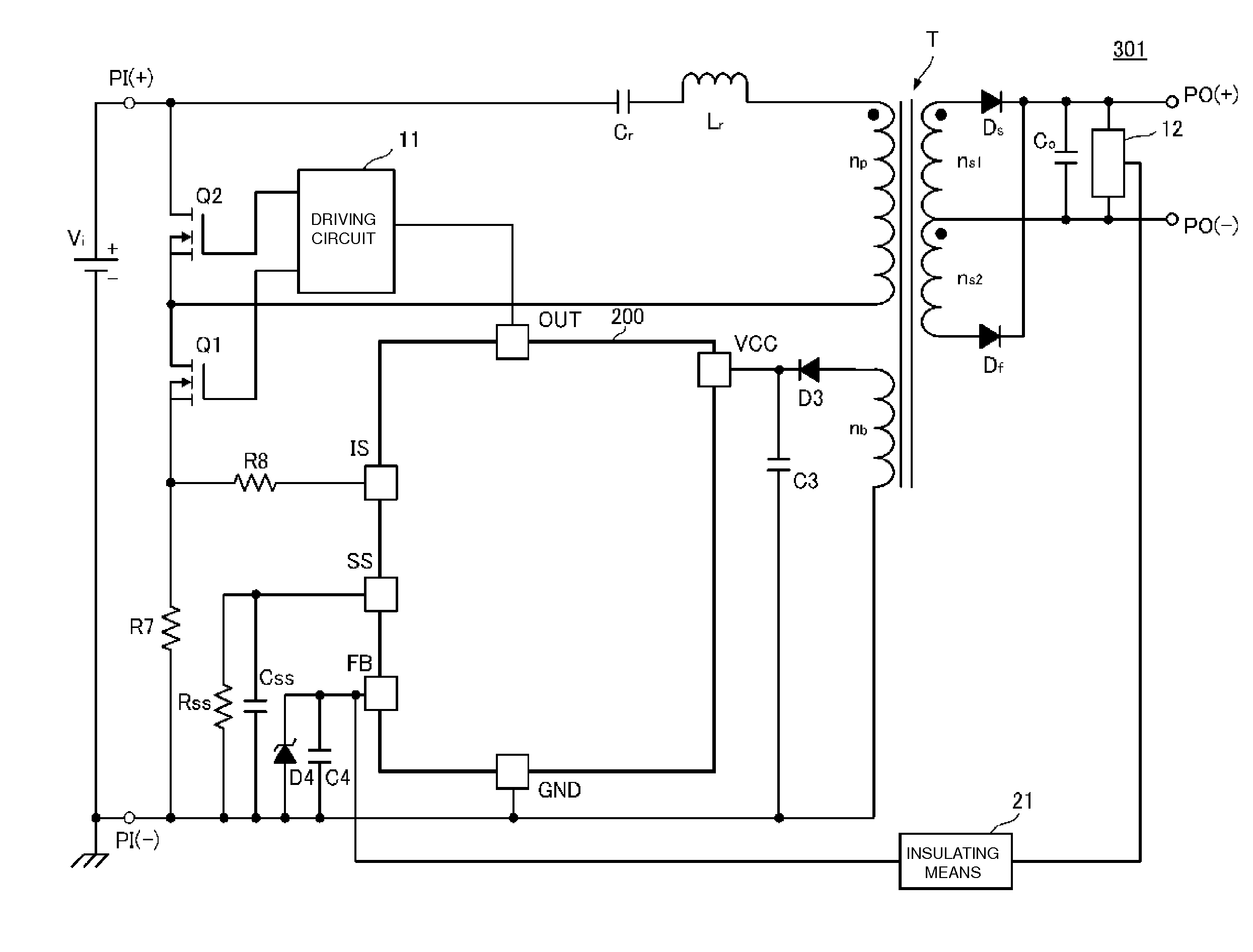
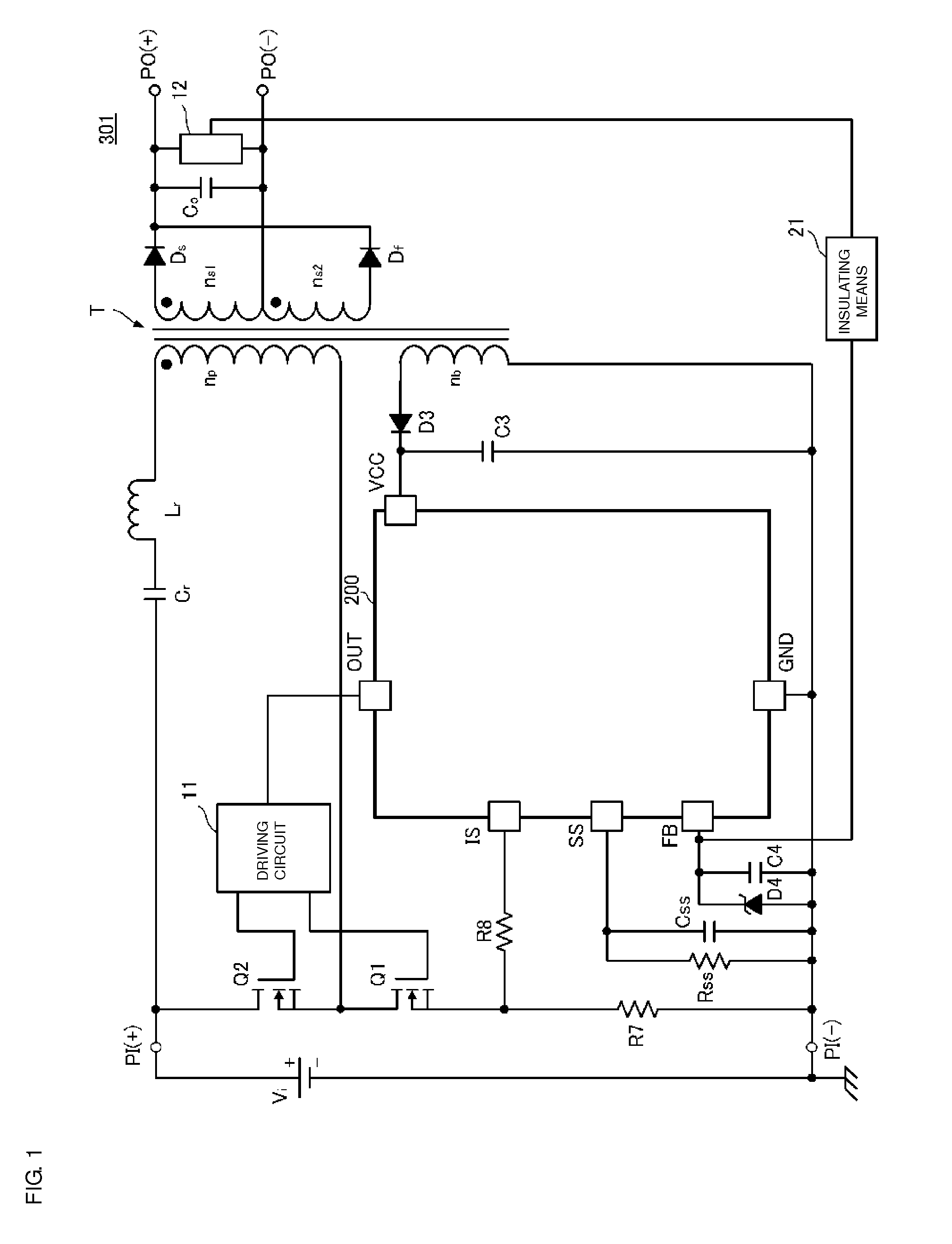
[0039]FIG. 1 is a circuit diagram of a switching power supply apparatus 301 according to a first preferred embodiment of the present invention. The switching power supply apparatus 301 includes a switching control IC 200.

[0040]A voltage of a DC input power supply Vi is input between input terminals PI(+)-PI(−) of the switching power supply apparatus 301. A predetermined DC voltage is output to a load connected between output terminals PO(+)-PO(−) of the switching power supply apparatus 301.

[0041]A first series circuit including a resonant capacitor Cr, a resonant inductor Lr, a primary winding np of a transformer T, a first switch device Q1, and a current detection resistor R7 connected in series with one another is provided between the input terminals PI(+)-PI(−). The first switch device Q1 preferably is defined by an n-type MOSFET, whose drain terminal is connected to the primary winding np and whose source terminal is connected to the current detection resistor R7.

[0042]A second ...

second preferred embodiment

[0079]FIG. 9, FIG. 10, and FIG. 11 are circuit diagrams of switching power supply apparatuses 302A, 302B, and 302C according to a second preferred embodiment of the present invention. In each of the switching power supply apparatuses 302A, 302B, and 302C, the secondary side of the transformer T preferably is of the forward type. In this manner, a forward system preferably is used by providing a rectifying and smoothing circuit including diodes Ds and Df, an inductor Lro, and a capacitor Co on the secondary side of the transformer.

[0080]The switching power supply apparatuses 302A and 302B differ in terms of a position at which the primary side capacitor Cr is connected. The primary side capacitor Cr need only be inserted in series into a closed loop defined during the on time of the high-side switch device Q2 and, hence, the capacitor Cr may be connected in series with the drain of the switch device Q2, as illustrated in FIG. 10.

[0081]The switching power supply apparatus 302C is a si...

third preferred embodiment

[0082]FIG. 12, FIG. 13, and FIG. 14 are circuit diagrams of switching power supply apparatuses 303A, 303B, and 303C according to a third preferred embodiment of the present invention. In each of the switching power supply apparatuses 303A, 303B, and 303C, the transformer T preferably is of the flyback type, and a rectifying and smoothing circuit including a diode Ds and a capacitor Co is provided on the secondary side of the transformer T. In this manner, a flyback system preferably is used.

[0083]The switching power supply apparatuses 303A and the switching power supply apparatuses 303B differ in terms of a position at which the primary side capacitor Cr is connected. The primary side capacitor Cr need only be inserted in series into a closed loop defined during the on time of the high-side switch device Q2 and, hence, the capacitor Cr preferably is connected in series with the drain of the switch device Q2, as illustrated in FIG. 13.

[0084]The switching power supply apparatuses 303C...


PUM


Abstract

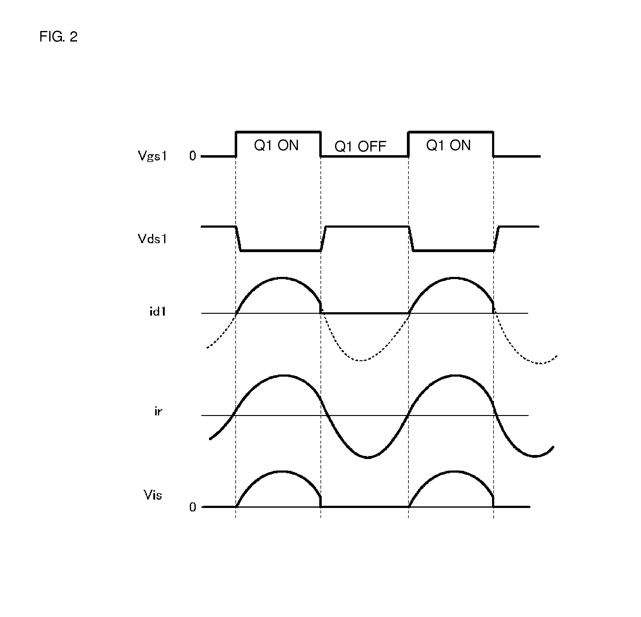
In a switching power supply apparatus, when it is detected at time t1 that a voltage Vis has exceeded a first threshold Vth1, a timer counting a period of time T1 is started, and the number times the input voltage Vis does not exceed Vth1 is started to be counted. When the timer expires before the count reaches a predetermined number, a first overcurrent protection operation is performed. When it is detected at time t2 that Vis has exceeded a second threshold Vth2, a second overcurrent protection operation is immediately performed. As a result, appropriate overcurrent protection is performed in accordance with the operating state of a load.

Description

BACKGROUND OF THE INVENTION[0001]1. Field of the Invention[0002]The present invention relates to a switching power supply apparatus, and specifically to a switching power supply apparatus provided with an overcurrent protection function.[0003]2. Description of the Related Art[0004]A switching power supply apparatus includes a power conversion circuit that converts an input voltage input from an input power supply into an output voltage supplied to a load, a switch device that switches the input voltage, a switching control circuit that controls the switch device, and the like. The switching control circuit is provided with an overcurrent protection function of protecting the switch device, a diode, an inductor, and the like against problems such as overheating or damage of components due to, for example, an overcurrent. For example, Japanese Unexamined Patent Application Publication No. 2008-206271 discloses a switching power apparatus configured to limit input / output power by turni...

Claims


Application Information

Patent Timeline
Patent Type & Authority Applications(United States)
IPC IPC(8): H02M3/335H02M1/32H02M1/00
CPCH02M3/33546H02M3/33507H02M1/32H02H3/093H02M1/36Y02B70/10H02M1/0058
Inventor HOSOTANI, TATSUYAYAMAGUCHI, NAOKI
Owner MURATA MFG CO LTD
Learn More