
Receiving stage and method for receiving

a technology for receiving stage and receiving signal, which is applied in the direction of transmission, line-faulst/interference reduction, modulated carrier system, etc., can solve the problems of inability to guarantee the receiving of short signal sequence (short data telegram), and the adjustment of amplification gain by using automatic gain control takes time, so as to achieve a wide input dynamic range, high amplification gain, and low amplification gain

Active Publication Date: 2014-12-25
FRAUNHOFER GESELLSCHAFT ZUR FOERDERUNG DER ANGEWANDTEN FORSCHUNG EV
View PDF27 Cites 0 Cited by
  • Summary
  • Abstract
  • Description
  • Claims
  • Application Information

AI Technical Summary

Benefits of technology

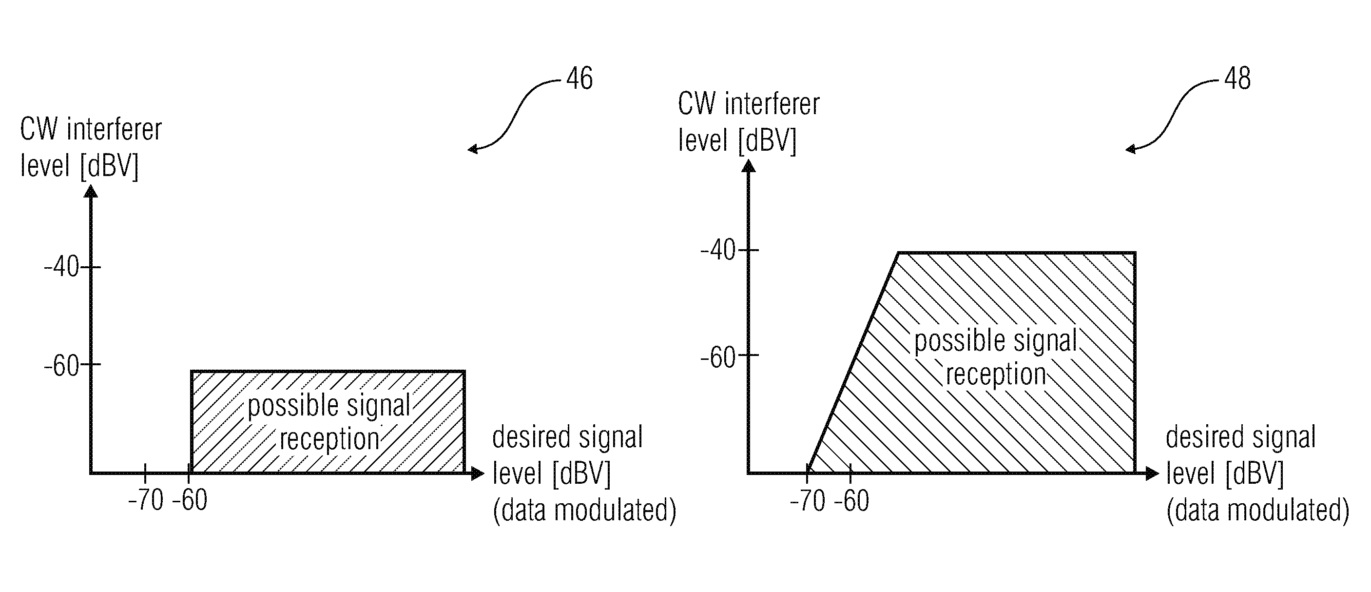
This patent describes a method for processing signals using multiple receiving paths with different amplification gains and comparators to evaluate the signal strength. The method allows for immediate processing of signals having different strengths without the need for adjusting the amplification gain. This results in a wider input dynamic range and reduces the risk of missing telegrams, especially in the case of OOK modulation. The method improves the immunity against interference while keeping the time advantage compared to state-of-the-art receivers. Overall, this patent provides a solution for improving the performance of receivers in challenging conditions.

Problems solved by technology

However, the adjustment of the amplification gain by using the automatic gain control takes time.
Therefore, it cannot be guaranteed that a short signal sequence (short data telegram) may be received especially in case of signal strength changes (strong to weak or vice versa).

Method used


Image

  • Receiving stage and method for receiving
  • Receiving stage and method for receiving
  • Receiving stage and method for receiving

Examples


Embodiment Construction

[0022]Different embodiments of the present invention will subsequently be discussed referring to FIGS. 1 to 3. In advance, identical reference numbers are provided to objects having identical or similar functions so that objects referred to by identical reference numbers within the different embodiments are interchangeable and the description thereof is mutually applicable.

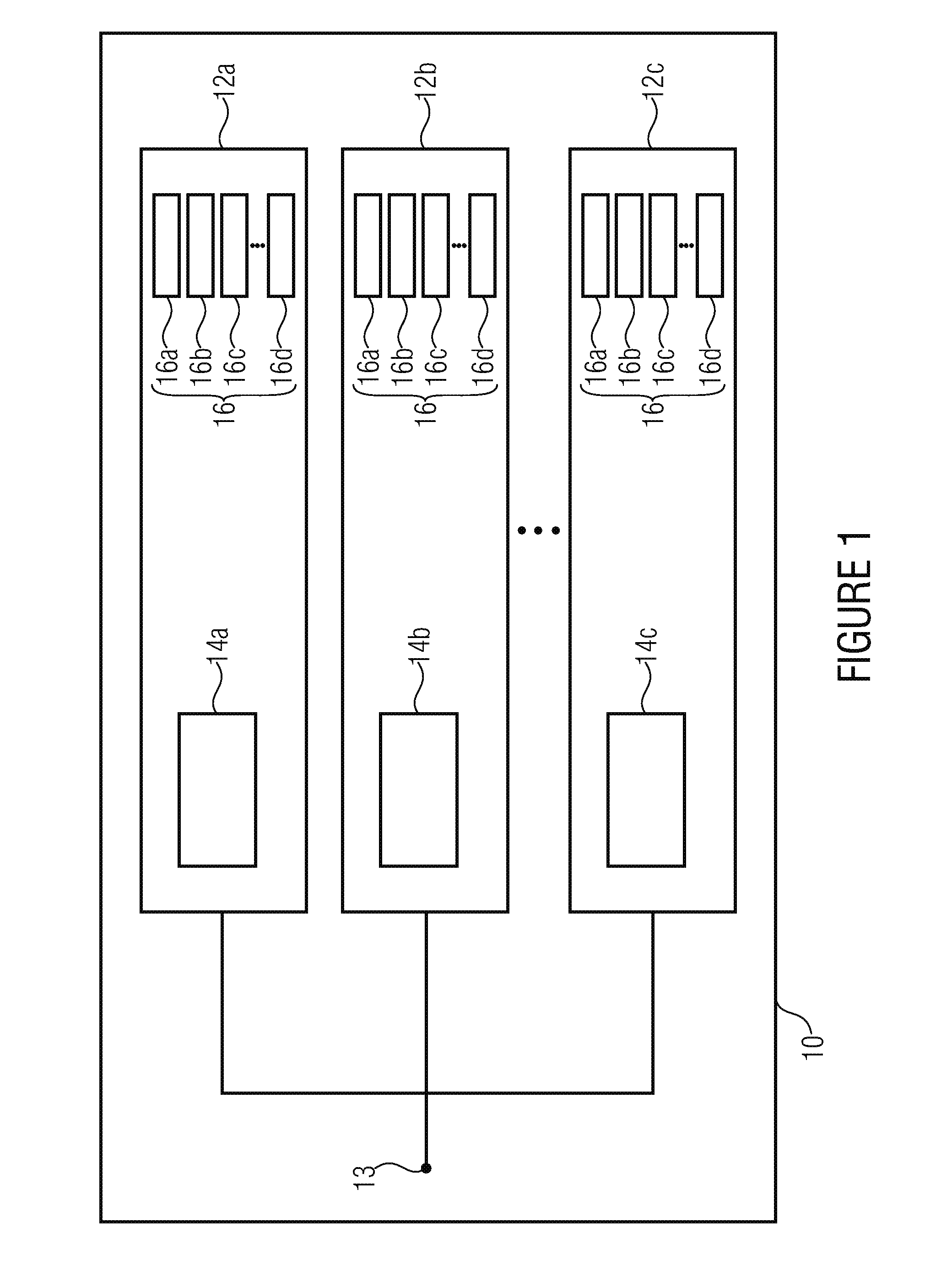
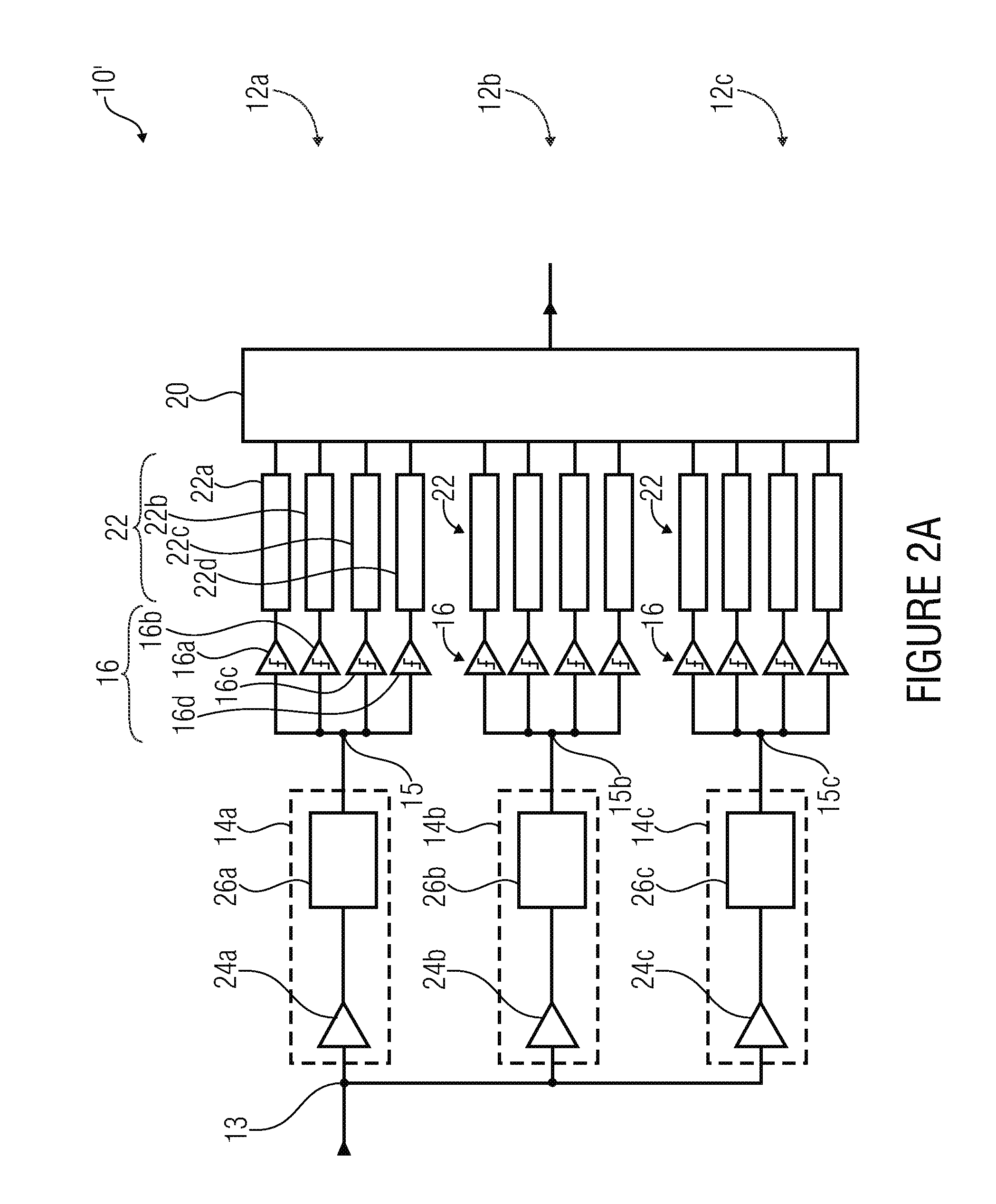
[0023]FIG. 1 shows a receiving stage 10 comprising M receiving paths 12a, 12b and 12c (M branches), wherein each receiving path comprises a signal processor 14a, 14b and 14c and K comparators 16a, 16b, 16c and 16d (K subbranches). The M receiving paths 12a, 12b and 12c are coupled to each other, for example via a common node 13, at the input side in order to receive the same receive signal (IF signal), for example from a mixing stage.

[0024]This receive signal is processed or amplified by each of the signal processors 14a, 14b and 14c and output to the respective comparator arrangement 16 of the respective receivin...


PUM


Abstract

A receiver stage for receiving a receive signal comprises M receiving paths, each receiving path comprises a signal processor and K comparators. The signal processors of the M receiving paths are configured to generate, for each of the M receiving paths, an amplified version of the receive signal, such that an amplification gain of the respective receiving path increases from a first of the M receiving paths to a last of the M receiving paths. For each of the M receiving paths the K comparators of the respective receiving paths are configured to compare the amplified receive signal of the respective receiving path with a respective threshold value. For each of the M receiving paths the threshold value increases from a first of the K comparators to the last of the K comparators.

Description

CROSS-REFERENCE TO RELATED APPLICATIONS[0001]This application is a continuation of copending International Application No. PCT / EP2013 / 054523, filed Mar. 6, 2013, which claims priority from U.S. Provisional Application No. 61 / 607,320, filed Mar. 6, 2012, each of which is incorporated herein in its entirety by this reference thereto.BACKGROUND OF THE INVENTION[0002]Embodiments of the present invention refer to a receiving stage for receiving a receive signal and to a method for receiving a receive signal.[0003]A receiving stage is typically included by a receiver, e.g. a communication receiver or radio receiver. All types of radio receivers have the purpose of converting the information carried by the radio waves to a useable form, e.g. an audio signal or a (digital) data signal. Such wireless receivers are typically coupled to an antenna for receiving the electromagnetic wave or the RF signal (radio frequency signal).[0004]The receiver typically comprises a receiving stage and a mixi...

Claims


Application Information

Patent Timeline
Patent Type & Authority Applications(United States)
IPC IPC(8): H03G3/30H04L27/06H04L25/08
CPCH03G3/3052H04L27/06H04L25/08
Inventor OEHLER, FRANKEPPEL, MARKUSMILOSIU, HEINRICH
Owner FRAUNHOFER GESELLSCHAFT ZUR FOERDERUNG DER ANGEWANDTEN FORSCHUNG EV
Learn More