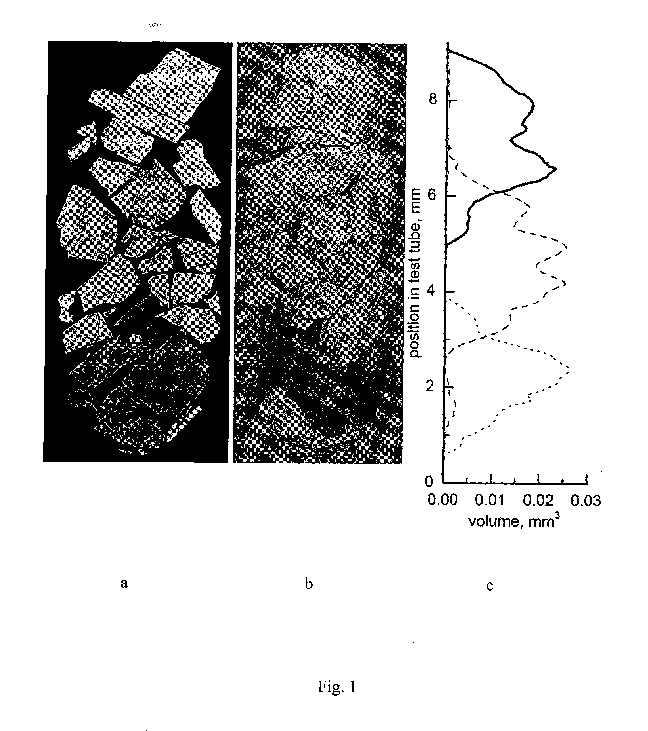
Method for 3D mineral mapping of a rock sample

a mineral mapping and rock sample technology, applied in material analysis using wave/particle radiation, instruments, nuclear engineering, etc., can solve the problem that the application does not disclose any procedures dealing with the location of objects

Inactive Publication Date: 2014-12-25
SCHLUMBERGER TECH CORP
View PDF4 Cites 16 Cited by
  • Summary
  • Abstract
  • Description
  • Claims
  • Application Information

AI Technical Summary

Benefits of technology

[0004]A method that allows providing an adequate geometry of a pore space and to perform mapping of minerals inside a sample is p

Problems solved by technology

However, the application does not disclose any procedures dealing with location of the ob

Method used


Image

  • Method for 3D mineral mapping of a rock sample

Examples


Embodiment Construction

[0013]Microtomography (microCT) and nanotomography (nanoCT) techniques can be used for adequate petrophysical characterization of the core sample via numerical modeling of the monophase and multiphase flows in pores of the sample and for accurate numerical characterization of thermal, electrical, wettability and geomechanical properties of the rock sample. These rock properties are essential for oil / gas reservoir exploration and management. The three dimensional (3D) mineral mapping can also find multiple applications in characterizing the rocks with non-hydrocarbon mineral resources (like rocks with coal or / and different metals), for instance, in the mining industry.

[0014]Different minerals have different chemical content (chemical elements) and density. In the other words, the minerals possess different contras in X-ray back projection and might be differentiated by their X-ray absorption coefficients:

I=I0e−μl

[0015]I—X-ray radiation intensity after l length propagation, I0—initia...


PUM


Abstract

The method for 3D mineral mapping of a rock sample comprises the steps of defining a total mineral content of a sample and calculating X-ray attenuation coefficients for the defined minerals. X-ray micro/nanoCT scanning of the sample is performed and its three-dimensional microstructure image in gray scale is obtained. Characteristic grayscale levels in the image corresponding to calculated X-ray attenuation coefficients and accordingly to the minerals are allocated and the 3D mineral map of the interior of the sample is provided.

Description

FIELD OF THE INVENTION[0001]The invention relates to X-ray based analysis of a core sample, namely microtomography (microCT) and nanotomography (nanoCT) techniques.BACKGROUND OF THE INVENTION[0002]X-ray micro- and nano-computed tomography is a well-known non-destructive technique for visualizing and quantifying the internal structure of objects in three dimensions (3D). It is used to provide high resolution images of rocks in 2D or 3D at a micron scale (see, for example, M. A. Knackstedt et al., “Digital Core Laboratory: Properties of Reservoir Core Derived From 3D Images,” SPE 87009, 2004).[0003]The idea of linking the gray values in 3D microCT image with densities is reflected in United States Patent Application Publication Number 2005 / 0010106. However, the application does not disclose any procedures dealing with location of the objects with different densities and chemical composition, such as different mineral grains.SUMMARY OF THE INVENTION[0004]A method that allows providing ...

Claims


Application Information

Patent Timeline
IPC IPC(8): G01N23/04G01N23/223G01N33/24G01N23/207
CPCG01N23/046G01N33/24G01N23/223G01N23/2076G01N2223/04G01N2223/402G01N2223/616G01N2223/419
Inventor KOROTEEV, DMITRY ANATOLIEVICHMUTINA, ALBINA RISHATOVNANADEEV, ALEXANDER NIKOLAEVICHGURPINAR, OMER M.
Owner SCHLUMBERGER TECH CORP
Why Eureka
Try Eureka