Mobile dry material storage

Active Publication Date: 2014-12-25
SOURCE LOGISTICS LTD O A AMMOS FIELD SOLUTIONS +1
View PDF8 Cites 67 Cited by
  • Summary
  • Abstract
  • Description
  • Claims
  • Application Information

AI Technical Summary

Benefits of technology

[0008]Particular embodiments of the bins include legs or other bin-support structure surrounding the discharge outlet. The bins are supported on the legs or other bin-support structure when positioned on the skid. Since the legs and, illu

Problems solved by technology

In particular, we have come to recognize that a particularly disadvantageous aspect of the prior art silo units arises from the fact that each unit brought to the site is a discrete system.
This means that the silo units must be individually filled pneumatically, giving rise to the above-noted problems inherent in that approach.
Another problem is that it can take quite a lot of time—

Method used


Image

  • Mobile dry material storage
  • Mobile dry material storage
  • Mobile dry material storage

Examples


Embodiment Construction

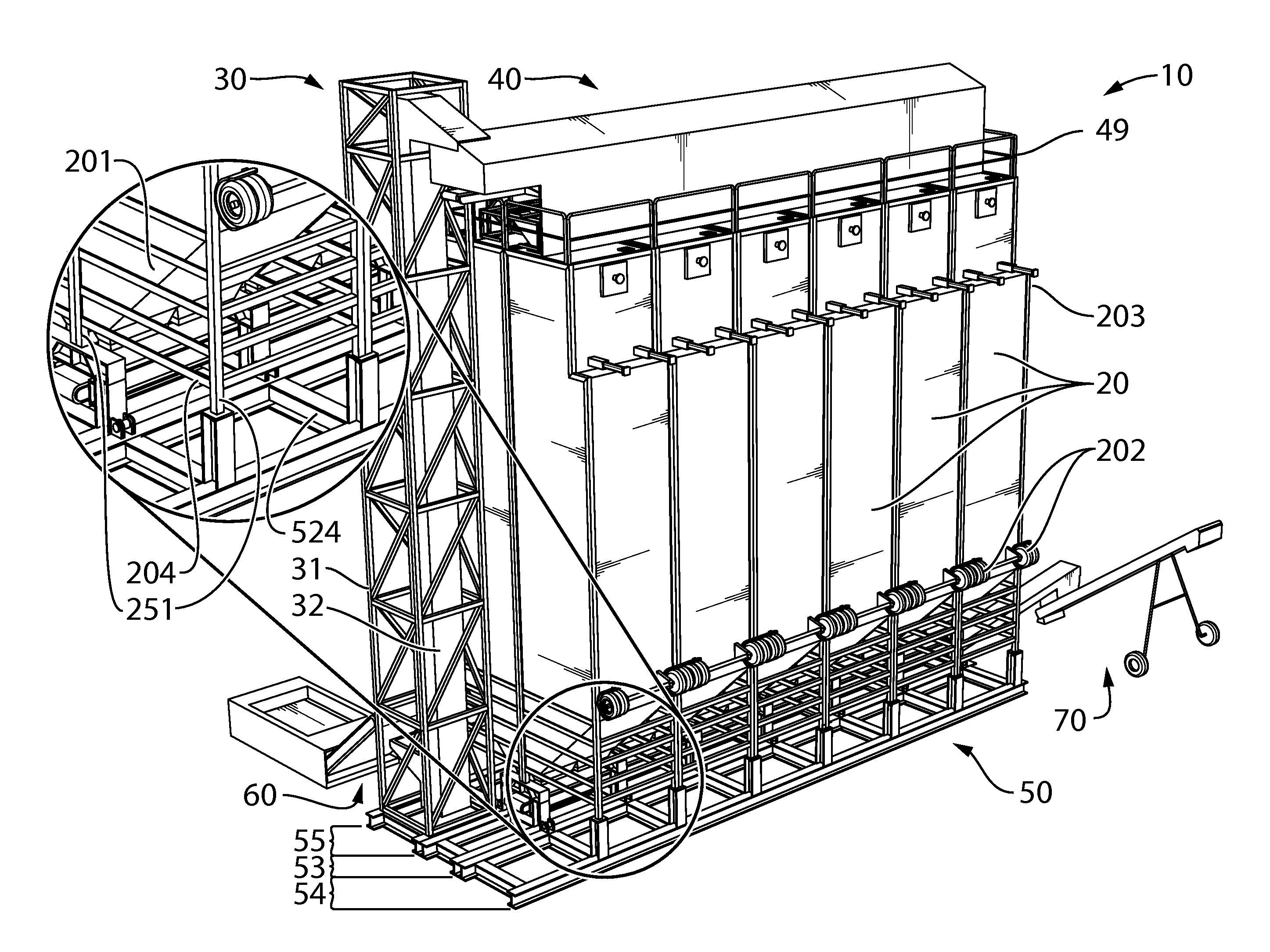
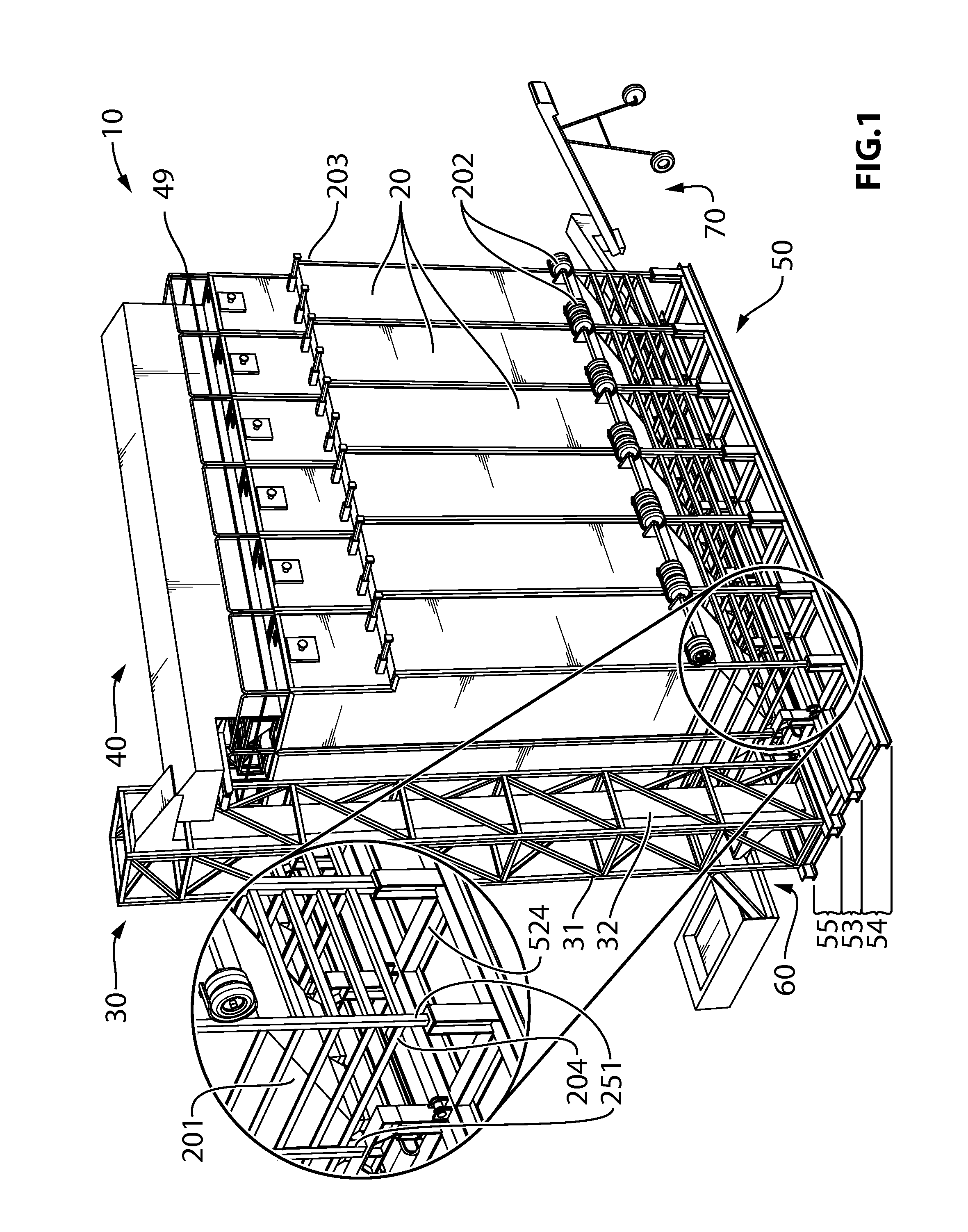
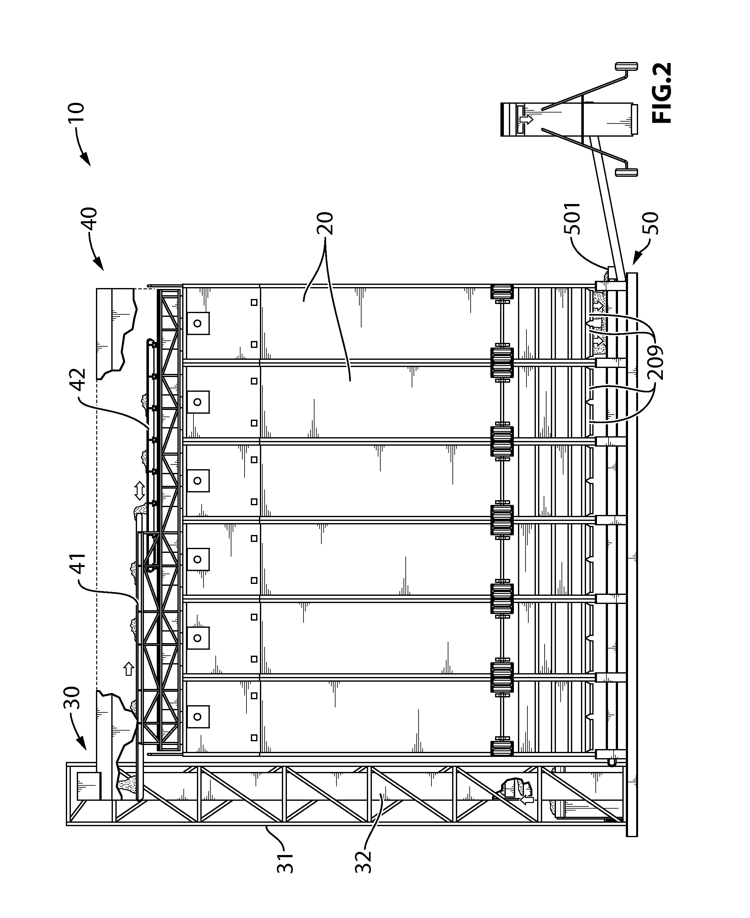
[0021]Reference is first made to FIGS. 1-5 depicting various views of an illustrative system 10 embodying the principles of the present invention, the system having been assembled and ready to receive and store sand or other material and to thereafter discharge same.

[0022]System 10 includes a plurality of elongate storage bins 20 which are substantially rectangular in cross-second over the majority of their length so as to comprise an elongate box in which sand or other material can be stored. Bins 20 are positioned vertically upright on a base structure, or “skid,”50 in at least one line—illustratively touching, or at least very close to, one another. In this embodiment, there are 12 bins arranged in two lines of 6 bins each. Each bin 20 has a discharge end 201 through which product in the bins can be discharged downwardly via gravity feed. Discharge end 201 includes a discharge outlet 209 that can be closed and opened (via a mechanism not shown) to controllably dispense sand or ot...


PUM

PropertyMeasurementUnit
Lengthaaaaaaaaaa
Heightaaaaaaaaaa

Abstract

A system that can be assembled at a well drilling or other site for storing bulk material such as sand includes a plurality of storage bins configured as trailers, a skid that includes a lower conveyor, a bucket elevator and a top conveyor system. At the site, the bins and the elevator are vertically oriented and stood on the skid, resulting in discharge outlets on the bins becoming positioned over the lower conveyor. The top conveyor is installed on top of the bins. In operation, the elevator lifts the material and discharges it onto the top conveyor system. The top conveyor system discharges the material into the bins for storage. The stored material is controllably discharged from the discharge outlets of the bins onto the lower conveyor from which the material is conveyed to one end of the skid for transport to a new location or directly into a blender.

Description

BACKGROUND[0001]The present invention relates to the handling, storing, and distribution of bulk dry materials, such as sand.[0002]There are many applications in which it is necessary to store large amounts of bulk dry material at a site. The following description gives the background of the invention in the context of one such application—the handling, storage and distribution of silica sand used as a proppant at a gas or oil well site in carrying out the process known as hydraulic fracturing, or “fracking.” It should be understood, however, that the invention is not so limited.[0003]The conventional prior art approach to storing sand at a well site is to place storage trailers horizontally on the ground and load and unload the sand using pneumatics. Disadvantageously, this requires a large footprint on the site, which has an impact on site lease costs and has environmental impacts as well. Other problems with this approach include inefficient use of trucking equipment, increased c...

Claims


Application Information

Patent Timeline
IPC IPC(8): B65G65/30B62D65/00B62D63/08
CPCB65G65/30B62D65/00B62D63/08B65G63/008Y10T29/49826
Inventor MCMAHON, JIM
Owner SOURCE LOGISTICS LTD O A AMMOS FIELD SOLUTIONS
Why Eureka
Try Eureka