Robotic mower navigation system

a robotic mower and navigation system technology, applied in the direction of distance measurement, process and machine control, instruments, etc., can solve the problems of difficult to predict the exact path traveled by the robotic mower, odometry may not match the actual distance traveled, and significant distance measurement errors over typical boundary wires. achieve the effect of high precision and high accuracy

Active Publication Date: 2014-12-25
DEERE & CO
View PDF18 Cites 44 Cited by
  • Summary
  • Abstract
  • Description
  • Claims
  • Application Information

AI Technical Summary

Benefits of technology

[0004]A robotic mower navigation system includes a plurality of sensors on a robotic mower that detect strength and polarity of a magnetic field from an electric current through a boundary wire. An electronic control unit receives data concerning the magnetic field from the plurality of sensors as the robotic mower follows the boundary wire, tracks the data provided by the sensors, compares the data with a reference pattern that defines at least one specified feature of the boundary wire, and provides commands to the robotic mower based on the comparison.

Problems solved by technology

However, wheel slippage caused by traction lost on wet grass, loose dirt, side hill compensation to drive in a straight line, or other reasons may result in significant distance measurement errors over typical boundary wires.
Distances measured by odometry may not match actual distances traveled by robotic mowers, and it is challenging to pr

Method used


Image

  • Robotic mower navigation system
  • Robotic mower navigation system
  • Robotic mower navigation system

Examples


Embodiment Construction

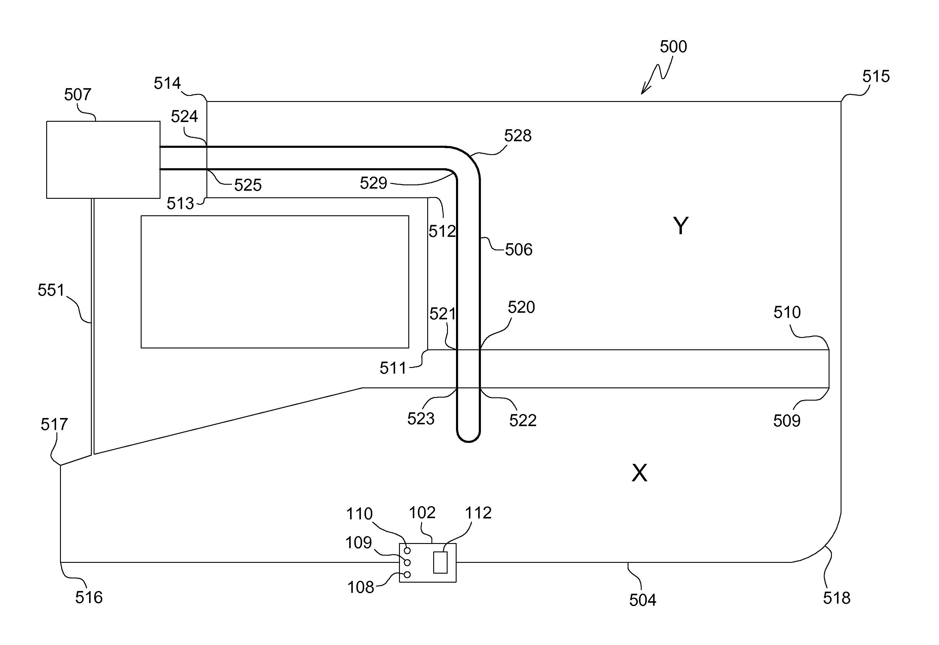
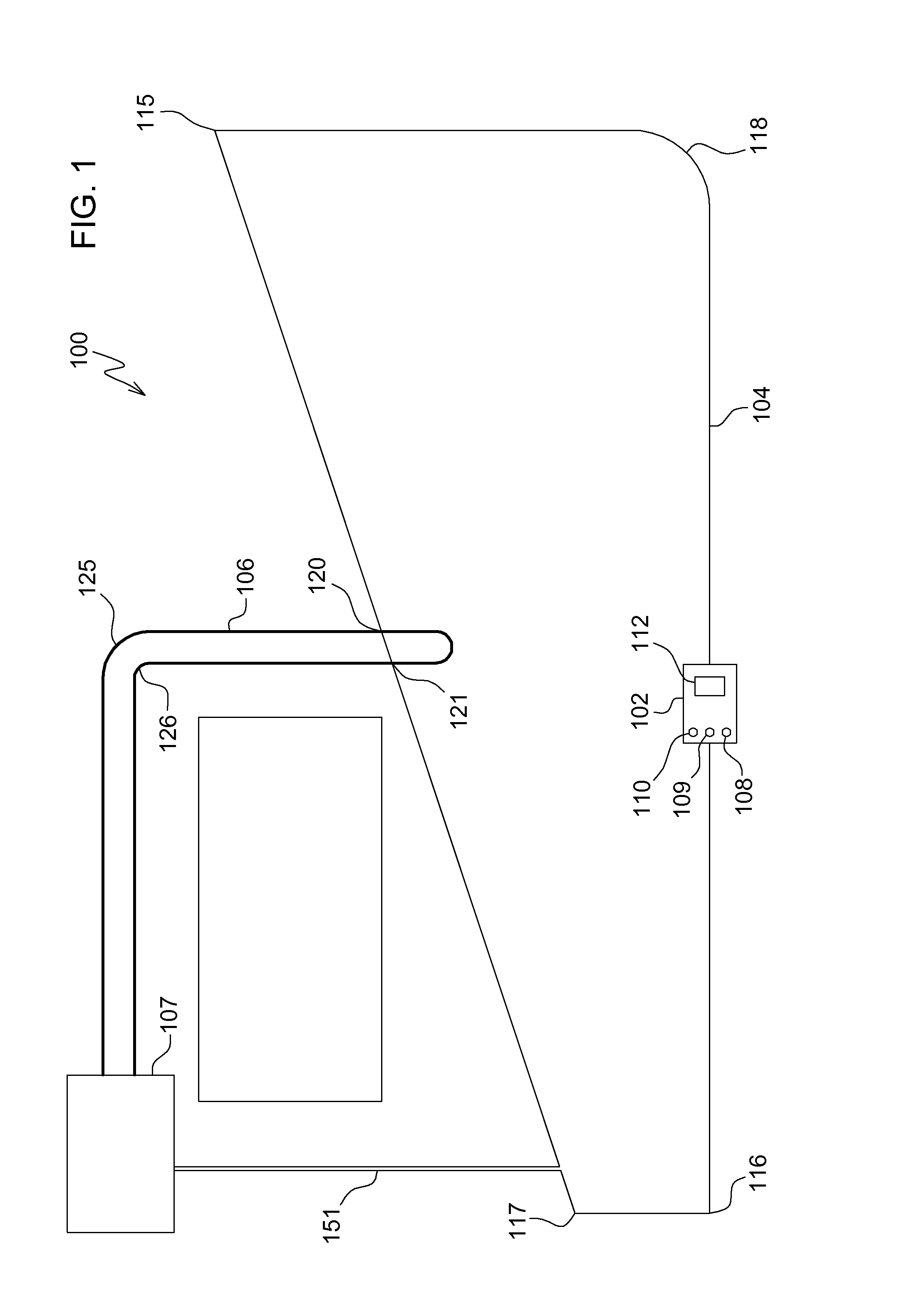
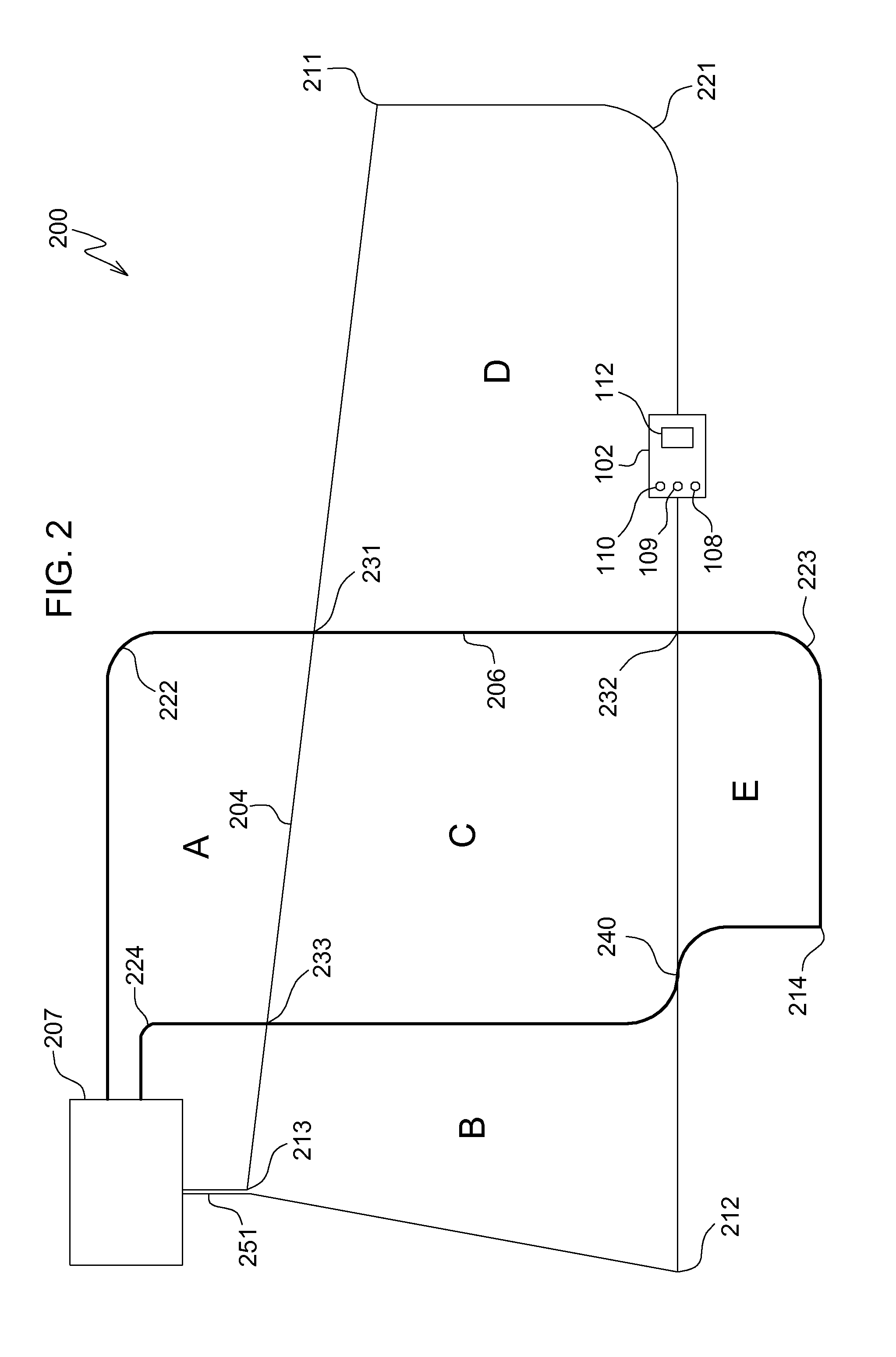
[0010]In one embodiment shown in FIG. 1, robotic mower navigation system 100 includes robotic mower 102 that may detect certain features of one or more boundary wires 104, 106 that may be encountered while the robotic mower travels along either boundary wire. Each boundary wire may form a loop with both ends of the loop connected to charging station 107 which provides current pulses that create an electromagnetic field along the wire. Two or more boundary wire loops may be installed on the same general area and can be driven with current pulses having different characteristics such that those pulses can be clearly identified by digital signal processing on the robotic mower.

[0011]In one embodiment, robotic mower navigation system 100 may include a robotic mower having a plurality of sensors 108, 109, 110 that may be electrically connected to electronic vehicle control unit 112. Each sensor may include a coil that senses the polarity and strength of the electromagnetic field from the...


PUM


Abstract

A robotic mower navigation system includes a plurality of sensors on a robotic mower that detect strength and polarity of a magnetic field from an electric current through a boundary wire. An electronic control unit receives data concerning the magnetic field from the plurality of sensors as the robotic mower follows the boundary wire, tracks the data provided by the sensors, compares the data with a reference pattern that defines at least one specified feature of the boundary wire, and provides commands to the robotic mower based on the comparison. The electronic control unit may command the robotic mower to follow a second boundary wire to a remotely located charging station instead of the first boundary wire based on detected features of the boundary wire such as sharp corners or crossings.

Description

FIELD OF THE INVENTION[0001]This invention relates to robotic lawn mowers, and more specifically to robotic mower navigation systems.BACKGROUND OF THE INVENTION[0002]Robotic mower navigation systems direct travel of robotic mowers within yards or to specific locations or portions of yards by measuring distances traveled from known references (e.g., charging stations) following boundary wires. Robotic mower navigation systems may include electronic control units that collect odometry data by measuring wheel rotation. However, wheel slippage caused by traction lost on wet grass, loose dirt, side hill compensation to drive in a straight line, or other reasons may result in significant distance measurement errors over typical boundary wires. Distances measured by odometry may not match actual distances traveled by robotic mowers, and it is challenging to predict the exact paths traveled by robotic mowers. As a result, robotic mower navigation systems lack high accuracy to navigate to sp...

Claims


Application Information

Patent Timeline
IPC IPC(8): A01D34/00G05D1/02
CPCA01D34/008Y10S901/01G05D1/0265G05D1/021G05D1/0225G05D2201/0208B60L3/12B60L15/2036B60L2200/40B60L2240/12B60L2240/421B60L2240/461B60L2250/16B60L2260/32B60L2260/46Y02T10/7072Y02T90/14Y02T10/72B60L50/52B60L58/21B60L53/18Y02T10/64Y02T10/70Y04S30/12Y02T90/167
Inventor DA ROCHA, FRANCISCO O.HAHNENKAMP, SVENFOLEY, MARK
Owner DEERE & CO
Why Eureka
Try Eureka