Method for Operating a Double Clutch Transmission

a transmission and double clutch technology, applied in mechanical equipment, transportation and packaging, gearboxes, etc., can solve the problems of increasing the overall drag loss achieve the effect of improving the efficiency factor of the dual clutch transmission, simple and effective, and reducing the consumption of the drive uni

Inactive Publication Date: 2015-01-01
ZF FRIEDRICHSHAFEN AG
View PDF3 Cites 1 Cited by
  • Summary
  • Abstract
  • Description
  • Claims
  • Application Information

AI Technical Summary

Benefits of technology

[0011]This also means that the total losses in the dual-clutch transmission through the approach in accordance with the invention are smaller when compared to a conventional mode of operation of a dual-clutch transmission, with which, in the switched-off sub-transmission, a transmission ratio that is possibly to be engaged in the future is engaged or remains engaged, regardless of whether the transmission ratio engaged in the switched-off sub-transmission concerns a lower or a higher driving stage than the transmission ratio engaged in the switched-on sub-transmission.
[0012]If, after a delivery of a turning moment between a sub-transmission to be switched off and a sub-transmission to be switched on carried out by a change of transmission ratio in the area of a dual

Problems solved by technology

However, drag moments arise in the open clutch of the dual-clutch device allocated to the switched-off sub-transmission, which represent a power loss and impair the efficiency factor of a dual-clutch transmission in a scope that is not negligible, and thus unnecessarily increase the consumption of the drive unit, whereas such drag moments, in the clutches of

Method used


Image

  • Method for Operating a Double Clutch Transmission
  • Method for Operating a Double Clutch Transmission
  • Method for Operating a Double Clutch Transmission

Examples


Embodiment Construction

[0027]Reference will now be made to embodiments of the invention, one or more examples of which are shown in the drawings. Each embodiment is provided by way of explanation of the invention, and not as a limitation of the invention. For example features illustrated or described as part of one embodiment can be combined with another embodiment to yield still another embodiment. It is intended that the present invention include these and other modifications and variations to the embodiments described herein.

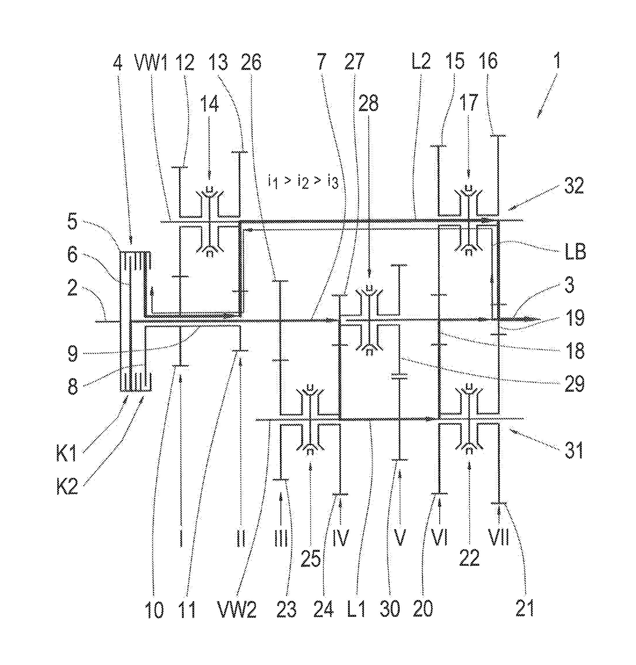
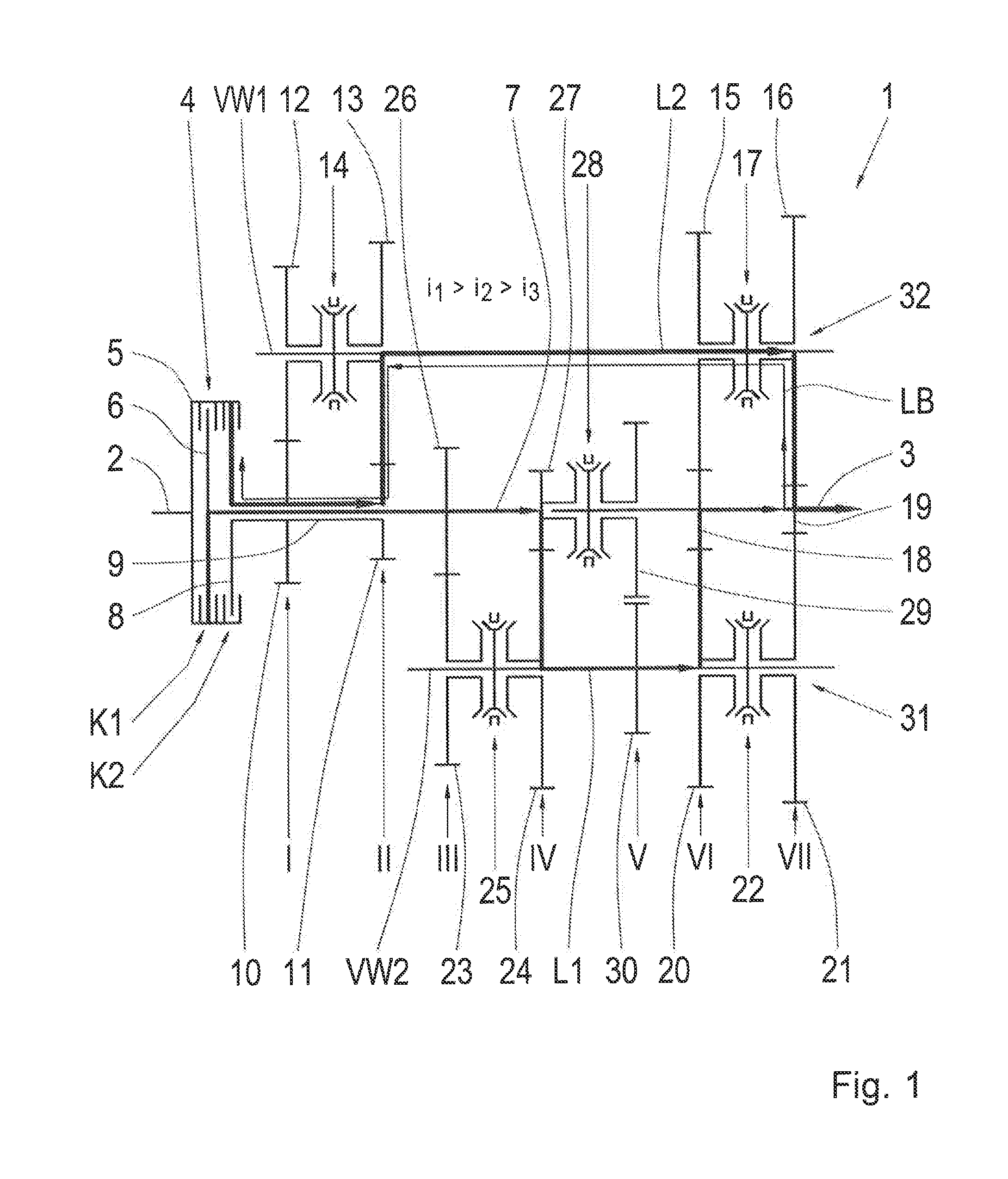
[0028]FIG. 1 shows a transmission diagram of a dual-clutch transmission 1 with a transmission input shaft 2 and a transmission output shaft 3. In a manner that is per se known, the transmission input shaft 2 is connected in a torque-proof manner to a dual-clutch device 4 in a common outer multi-disk carrier 5 of two clutches K1 and K2 of the dual-clutch device 4. An inner multi-disk carrier 6 of the clutch K1 is coupled in a torque-proof manner to a first transmission input shaft 7...


PUM


Abstract

A method for the operation of a dual-clutch transmission wherein, through a clutch of a dual-clutch device, sub-transmissions are able to be switched on in the power flux of the dual-clutch transmission or are able to be switched off from the power flux. In the sub-transmissions, two different transmission ratios are able to be engaged or disengaged through the actuation of shifting elements. In the operation of the dual-clutch transmission, one of the sub-transmissions is switched on, while the other sub-transmission is switched off. If the transmission ratio in the switched-on sub-transmission is engaged, all transmission ratios in the switched-off sub-transmission are simultaneously disengaged through the shifting elements, as long as there is no request for a change of transmission ratio in the dual-clutch transmission.

Description

FIELD OF THE INVENTION[0001]The invention relates to a method for operating a dual-clutch transmission.BACKGROUND[0002]Dual-clutch transmissions known in practice feature, in each case through a clutch of a dual-clutch device, sub-transmissions that are able to be switched on in the power flux of the dual-clutch transmission or are able to be switched off from the power flux, in which, in each case, at least two different transmission ratios are able to be engaged or disengaged through the actuation of shifting elements. In the operation of the dual-clutch transmission, essentially, one of the sub-transmissions is switched on, while the other sub-transmission is switched off, whereas the transmission ratio currently provided in the dual-clutch transmission is engaged in the switched-on sub-transmission, while, in the switched-off sub-transmission, an additional transmission ratio is engaged, which in the dual-clutch transmission in the future is to be engaged with a high probability...

Claims


Application Information

Patent Timeline
IPC IPC(8): F16H3/087
CPCF16H3/087F16H3/006F16H3/097Y10T74/19228F16H2200/0069F16H61/688F16H2061/0015F16H2306/18
Inventor ROHM, AXEL
Owner ZF FRIEDRICHSHAFEN AG
Why Eureka
Try Eureka