Cooking device
a technology for cooking devices and ovens, which is applied in the field of cooking devices, can solve the problems of poor apparatuses at preparing high-quality dishes, lowering the temperature, and not being able to maintain hot air at a lower temperature or raising hot air, and achieves the effects of reducing energy consumption, preventing steam, and reducing the number of calories
- Summary
- Abstract
- Description
- Claims
- Application Information
AI Technical Summary
Benefits of technology
Problems solved by technology
Method used
Image
Examples
first embodiment
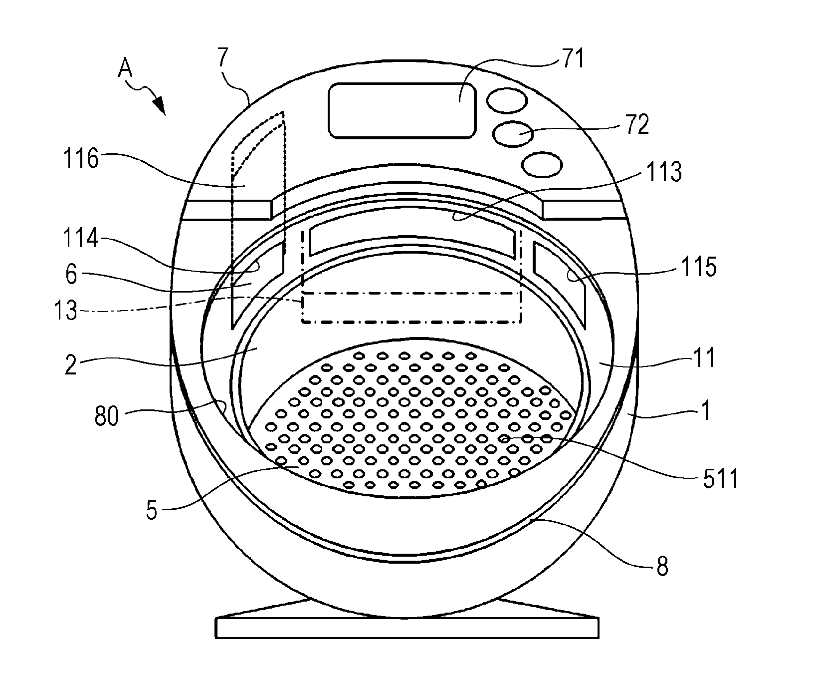
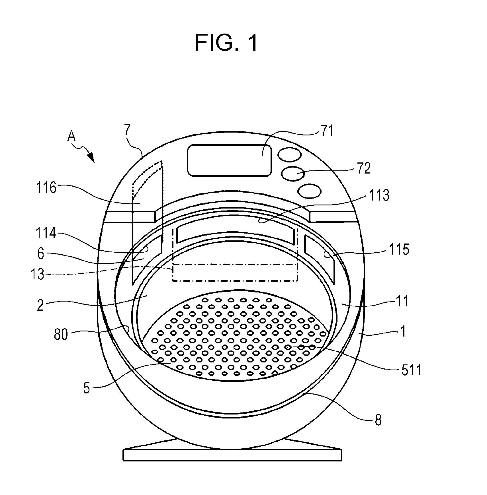
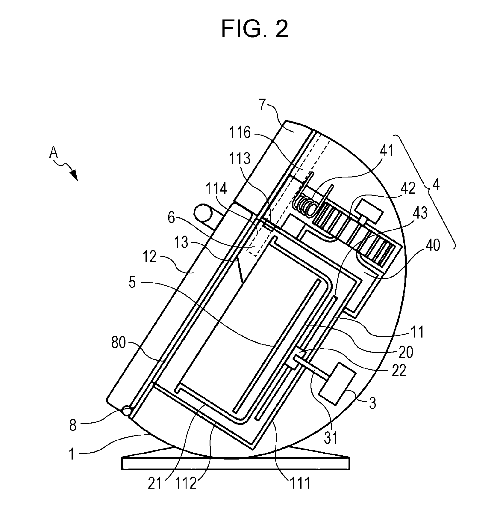
[0023]FIG. 1 is a front view of a cooking apparatus A according to a first embodiment of the present disclosure and FIG. 2 is a cross-sectional view of the cooking apparatus A illustrated in FIG. 1, viewed from the side. FIG. 1 does not illustrate a door from the cooking apparatus A for convenience sake.
[0024]The cooking apparatus A is an apparatus that performs a heating operation by blowing hot air to an object disposed inside of it. As illustrated in FIGS. 1 and 2, the cooking apparatus A includes a housing 1, an inner pan 2 (container), a motor (driving unit) 3 that drives the inner pan 2 to rotate, a heating unit 4 that generates hot air, an object receiving member 5 disposed in the inner pan 2 and on which an object is placed, an exhaust damper 6 (exhaust adjustment unit) that adjusts the flow rate of discharge of hot air, an operating unit 7, and a front board 8 disposed on the front side of the housing 1. The inner pan 2, the motor 3, and the heating unit 4 are disposed insi...
second embodiment
[0084]Referring to the drawings, a cooking apparatus according to a second embodiment of the present disclosure will be described. FIG. 7 is a block diagram of a cooking apparatus B according to another embodiment of the present disclosure. The cooking apparatus B illustrated in FIG. 7 includes a humidity detector 95 (humidity detecting unit) and other components are the same as those in the cooking apparatus A. Substantially the same components are denoted by the same reference symbols and are not described in detail.
[0085]The humidity detector 95 includes a humidity sensor that detects the internal humidity of the inner pan 2. The humidity detector 95 detects the humidity of hot air and transmits information of the humidity to the controller 91. Since the hot air inside the inner pan 2 is substantially identical with the hot air that circulates through the circulation flow path 40, the humidity of hot air that circulates through the circulation flow path 40 may be detected. At thi...
third embodiment
[0115]Now, a cooking apparatus according to a third embodiment of the present disclosure will be described. As illustrated in FIG. 1, the air outlet 113, the exhaust port 114, and the intake port 115 are positioned at an upper front portion of the outer pot 11. This positioning can hinder an object, water, or other objects from entering the air outlet 113, the exhaust port 114, and the intake port 115 when the object is taken in or out or at the maintenance of the outer pot 11, whereby problems concerning the maintenance of the cooking apparatus can be minimized.
[0116]In the case where the apparatus has a structure in which hot air is blown from an upper opening of the inner pan 2, the inner pan 2 does not have a portion that allows hot air to pass through other than the upper opening. The hot air that has been blown to the inner pan 2 thus bounces off the bottom portion of the inner pan 2. Then, the hot air that has blown out from the air outlet 113 is divided into two parts by the...
PUM
 Abstract
Description
Claims
Application Information
 - R&D
- Intellectual Property
- Life Sciences
- Materials
- Tech Scout
- Unparalleled Data Quality
- Higher Quality Content
- 60% Fewer Hallucinations
Browse by: Latest US Patents, China's latest patents, Technical Efficacy Thesaurus, Application Domain, Technology Topic, Popular Technical Reports.
© 2025 PatSnap. All rights reserved.Legal|Privacy policy|Modern Slavery Act Transparency Statement|Sitemap|About US| Contact US: help@patsnap.com


