Retarding system for an electric drive machine

a technology of electric drive machine and storage system, which is applied in the direction of machine control, mechanical control devices, instruments, etc., can solve the problems of system slowing down or in slippery conditions, unable to stop a high-speed machine quickly, and a configuration that is difficult for an operator to control effectively

Active Publication Date: 2015-01-01
CATERPILLAR INC
View PDF9 Cites 10 Cited by
  • Summary
  • Abstract
  • Description
  • Claims
  • Application Information

AI Technical Summary

Problems solved by technology

Although brake systems utilizing electric drive systems have been used, these systems cannot stop a machine traveling at high speed quickly, nor can these systems consistently slow a heavily loaded machine traveling downhill or in slippery conditions.
However, this configuration may be difficult for an operator to control effectively.
In a large, heavily loaded machine, this may lead to the service brakes overheating.
In addition, excess service brake wear may occur on a machine if the service brakes are used for continuous retarding.
However, the Ikeda reference does not disclose how to provide feedback to the truck's operator when the brake system transitions between hydraulic function and retarder function.

Method used


Image

  • Retarding system for an electric drive machine
  • Retarding system for an electric drive machine
  • Retarding system for an electric drive machine

Examples


Embodiment Construction

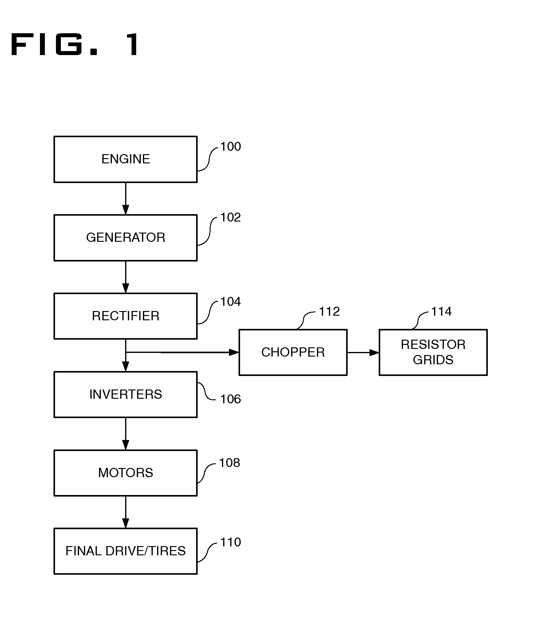
[0017]Referring to the drawings, FIG. 1 illustrates a schematic view of an exemplary electric drive system including an electric retarding system for a machine. The exemplary electric drive system includes an engine 100. Suitable engines include gasoline powered and diesel powered internal combustion engines. When in a drive configuration, the engine 100 powers a generator 102. The generator 102 produces three-phase alternating current. The three-phase alternating current passes through a rectifier 104, which converts the alternating current to direct current. An inverter or inverters 106 convert the direct current to variable frequency back to alternating current which feeds a motor 108. By controlling the frequency of the current produced by the inverters 106, the speed of the motor 108 is controlled. The motor 108 produces torque which powers the drive wheels 110.

[0018]In an alternative example of the current disclosure, an engine is not needed and the motor 108 is driven directl...


PUM


Abstract

A retarding system for an electric drive machine is provided. The retarding system includes an electrical retarding system and a hydraulic braking system. A single pedal controls both the electrical retarding system and the hydraulic braking system. The pedal includes a first range of travel that provides input to the electrical retarding system and a second range of travel that additionally controls the hydraulic braking system. The pedal further includes different levels of travel resistance in each of the two ranges of travel that correspond to providing inputs to the electrical retarding system and the hydraulic braking system.

Description

TECHNICAL FIELD[0001]This disclosure relates generally to braking systems, and, more particularly to braking systems and methods that combine electric retarding and friction braking to slow a machine.BACKGROUND[0002]Braking systems are used in a large variety of machines and vehicles to control, slow and stop the machine. Exemplary machines include passenger vehicles, trains, dump trucks, and mining vehicles. Machines increasingly use electric drive systems to provide propulsion for the machine. For example, passenger vehicles may use a hybrid drive system whereby a traditional gasoline powered engine and an electric motor are both used to provide propulsion for the vehicle. Machines, such as a railway engines and off-road vehicles may use a diesel-powered engine to drive a generator, which provides electric power to a motor. The motor then provides propulsion for the machine.[0003]Braking systems may take advantage of components in electric drive systems to provide braking for mach...

Claims


Application Information

Patent Timeline
Patent Type & Authority Applications(United States)
IPC IPC(8): B60W10/188B60W30/18B60W10/196G05G1/44B60W10/08
CPCB60W10/08B60W30/18109G05G1/44B60W10/188B60W10/196B60T1/10B60T7/042B60T13/586F16D61/00Y10T74/20528B60Y2300/89Y02T10/72
Inventor ANTAO, NISCHOLSTAUB, MICHAELBAILEY, BRADLEYCOPELAND, BRYANDABBS, HAROLD
Owner CATERPILLAR INC
Why Eureka
Try Eureka