Method and system for certifying the presence of an operator

a technology of operator and method, applied in the field of method and system for certifying the presence of an operator, can solve the problems of not allowing the presence to be certified with an adequate level of security, requires real-time transmission of entered data, and dedicated connection, etc., to achieve the effect of enhancing security, simplifying transmission and storage thereof, and less demanding

Inactive Publication Date: 2015-01-01
SIXS S R L SOLUZIONI INFORMATICHE PER IL SOCIALE
View PDF4 Cites 16 Cited by
  • Summary
  • Abstract
  • Description
  • Claims
  • Application Information

AI Technical Summary

Benefits of technology

[0017]Furthermore, it is advantageously possible to monitor, simultaneously and effectively, a plurality of users, even mobile ones, thanks to the use of the second device operable by the operator; in fact, a plurality of code generation devices having different identifiers are respectively associated with the various users. This allows certifying and monitoring at a central level the services provided by operators to different users.
[0018]In other words, the third validation device is additionally given a time indication relating to the time instant at which the code was requested, and an identifier of the user to whom it was requested. This information may be transmitted to the third validation device by the operator or, even automatically, by the second device. The presence code is then validated by comparing it with a second presence code, which is subsequently generated by the third validation device by using the same said encoding algorithm, as if it were generated at the same time instant as the request, and for the same user identifier. In this manner, by verifying the coherence between the information relating to the presence of the operator and the code generated and transmitted, it is possible to certify the presence of the operator by using presence codes having a reduced length, thereby simplifying the transmission and storage thereof by means of various different technologies.
[0019]This enhances security even further, while at the same time making it less exacting for the verification device to interpret the presence code.
[0020]In a preferred embodiment, the second device requests the generation of the presence code to the first device, which step may also occur automatically, e.g. when the two devices are brought near, even without touching each other. In this case, the first device transmits the presence code to the second device; also, the second device preferably transmits the presence code to the third validation device automatically, e.g. when it is connected thereto, whether physically or via a wireless connection, thereby allowing the data to be downloaded to the third validation device. The automation of the transmission of the presence code results in an easier certification procedure for the users and / or the operators.
[0021]Preferably, the presence code is transmitted by means of wireless devices, e.g. of the RFID or Bluetooth type, resulting in simpler and faster interaction between the devices. In a preferred embodiment, the distance between the first device and the second device, or the geographic position of at least one of said devices, is verified as soon as the presence code is requested, so that the code will only be generated or stored if the distance is shorter than a predetermined distance or the geographic position is within a predetermined area. This further improves certification security, since it prevents any abuse by the operator even should the user be his / her accomplice.
[0022]Preferably, the encoding algorithm generates codes having limited time validity and based on the current time. In this manner, it is possible to univocally certify the presence of the operator on the basis of the generated codes, as well as to improve the security of 20 the certification system by preventing any tampering.

Problems solved by technology

These known systems, however, although useful for automatic presence collection, do not allow presences to be certified with an adequate level of security, since identification badges can be easily transferred from one person to another, and the presences themselves can be easily altered before being transmitted to the customer.
The system known from US2005 / 0035863A1 has the drawback that it requires real-time transmission of the entered data, i.e. it requires the presence of a dedicated connection, which however might be difficult to install in many workplaces, such as domestic environments or open building sites.
The method and the apparatus described in WO91 / 06926, however, suffer from the drawback that, in order to verify at a central level the presence of individuals identified at multiple stations, all such multiple stations must be connected to one another, e.g. through a central processor.
A system like the one disclosed in WO91 / 06926 would therefore be difficult to install in many workplaces, such as, for example, domestic environments or open building sites.
The system known from WO2004 / 025575A1, however, suffers from the drawback that the information, though encoded, is transmitted in a non-optimal way as far as certification security is concerned.
Any tampering of the code according to WO2004 / 025575A1 would, in fact, create significant security problems, since all information, though encrypted, is contained in the code itself, and an ill-intentioned user would have access to it.
At the same time, the generated code may need to have a considerable length to be able to contain the encoded information; this fact may involve difficulties in the subsequent code transmission and storage steps.

Method used


Image

  • Method and system for certifying the presence of an operator
  • Method and system for certifying the presence of an operator
  • Method and system for certifying the presence of an operator

Examples


first embodiment

[0071]FIG. 3 illustrates the method, wherein the operator is required to provide information about the user identifier, the date, the time, and a stored presence code.

[0072]At step 201 the presence certification method starts; at step 202, a presence code is requested to attest the presence of the operator 101 at the user 102 at that given time instant.

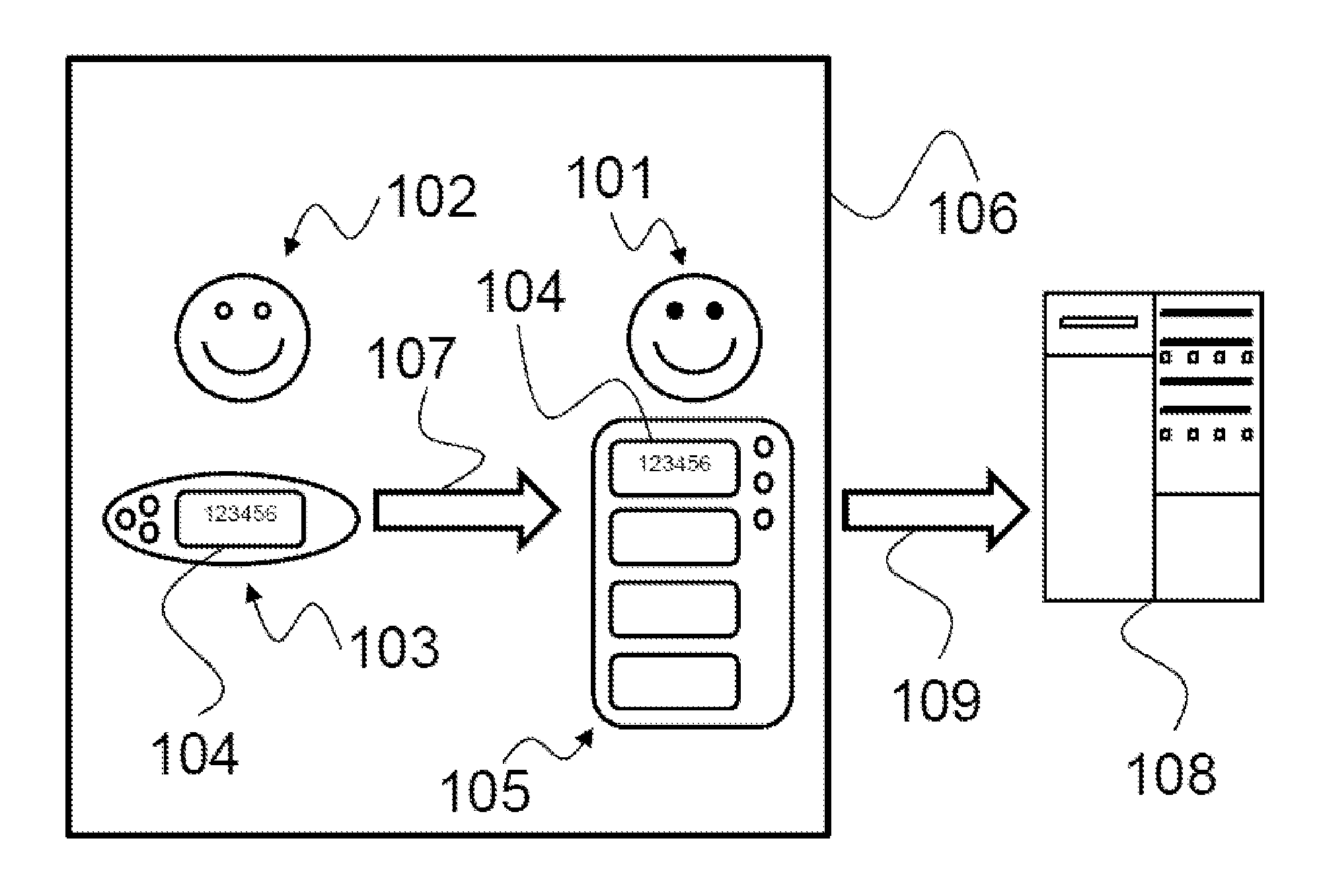
[0073]At step 203, the device 103 operable by the user 102 generates a TOTP presence code 104 to be transmitted to the operator.

[0074]At step 204, the device 105 operable by the operator 101 receives the code 104 and stores it into a permanent or volatile memory. The device 105 is in the proximity of the device 103. Storing may occur automatically or manually, in which case the operator 101 will write or enter the presence code.

[0075]In general, a digital medium will be used for storage purposes, but an analog one may be used as well. It is also conceivable that storage occurs on a non-digital medium, such as, for example, a pre-print...

second embodiment

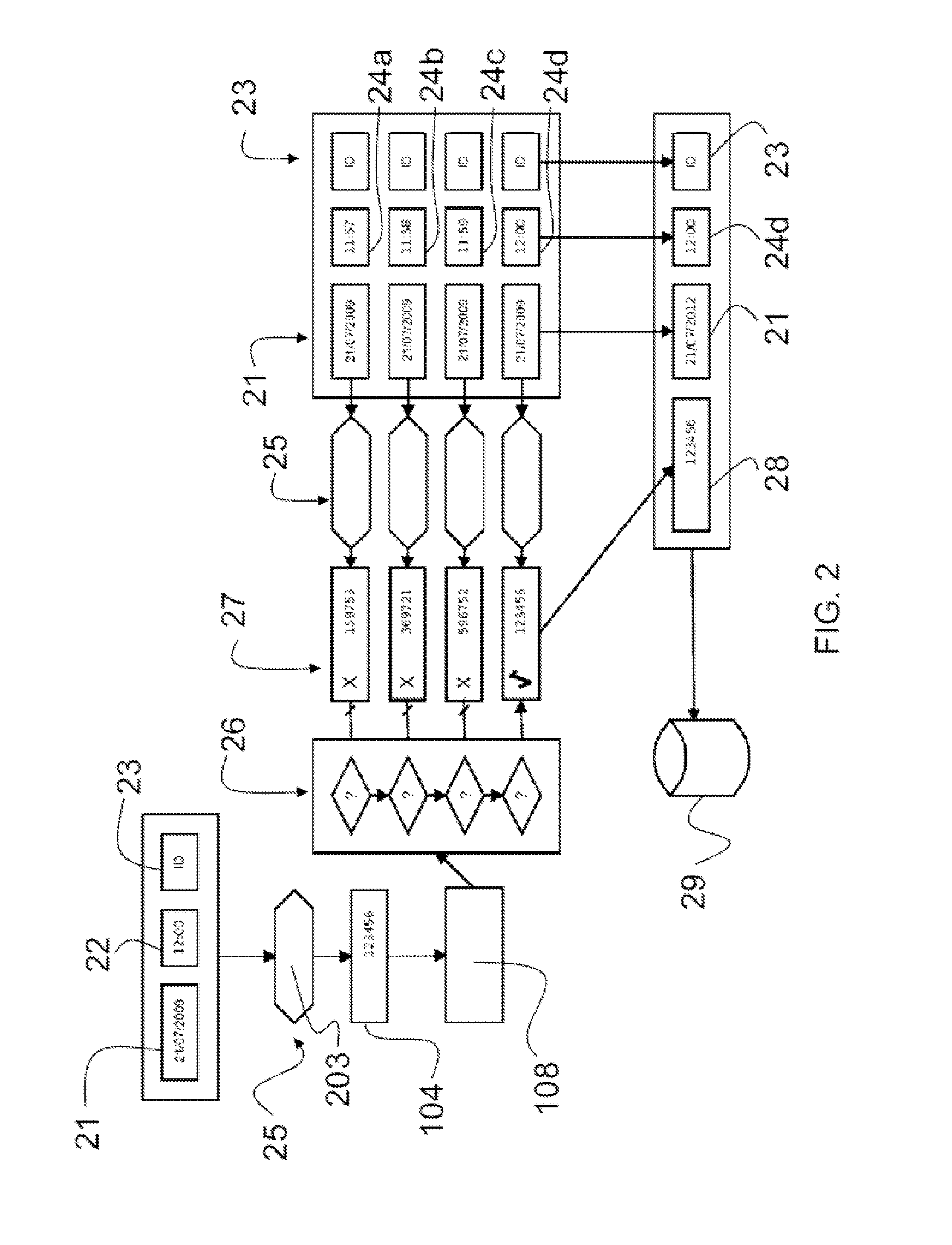
[0083]FIG. 4 illustrates the method, wherein the operator is required to signal a user identifier, the date, and a stored presence code. The validation device 108 automatically provides time recognition; this embodiment is particularly advantageous when the certification system is used as a “stamper”, so that the operator does not have to worry about the date / time.

[0084]At step 201 the presence certification method starts; at step 202, a presence code is requested; at step 203, the device 103 operable by the user 102 generates a presence code 104, which is then stored at step 204 by the device 105 operable by the operator; at step 205, the operator specifies the identifier of the device 103.

[0085]At step 306, the operator specifies the service date only, and this information is stored into the device 105.

[0086]At step 307, the device 105 sends to the validation device 108 the stored data, i.e.: presence code, date, user identifier.

[0087]At step 308, the remote validation device 108 ...

third embodiment

[0090]FIG. 5 illustrates the method, wherein the operator is only required to provide the user identifier and to store a presence code. The validation device 108 automatically recognizes the date of generation, which may be encoded, for example, in the presence code 104; this embodiment is also particularly advantageous when the certification system is used as a “stamper”, so that the operator does not have to worry about the date / time.

[0091]Furthermore, this embodiment is particularly advantageous because it ensures a higher level of system automation by requiring minimal human intervention.

[0092]At step 201 the presence certification method starts; at step 202, a presence code is requested; at step 203, the device 103 operable by the user 102 generates a presence code 104, which is then stored at step 204 by the device 105 operable by the operator.

[0093]At step 407, the device 105 sends to the validation device 108 the presence code stored together with the user identifier.

[0094]A...


PUM


Abstract

A method for certifying the presence of an operator includes a presence code (104) requested (202) at a given time instant (21, 22) to a first device (103) operable by a user (102); the first device (103) generates (203) the presence code (104), the presence code (104) including a portion generated according to an encoding algorithm (25), wherein the generated portion depends on the time instant (21, 22) and on an identifier (23) of the first device (103); a second device (105) operable by an operator (101) stores (204) the generated presence code (104); the presence code (104) is transmitted (109) to a third validation device (108); the third validation device (108) certifies (212) the presence of the operator (101) at the user (102) at the time instant (21, 22); the certification (212) including: providing the third validation device (108) with at least one piece of time information (21, 206, 306) about the time instant (21, 22), and further providing (205) the identifier (23) of the first device (103), wherein the presence code (104) is validated (208) by comparing it (26) with at least one second presence code (27) generated (25) by the third validation device (108) according to the same encoding algorithm (25) and according to the piece of time information (21, 206, 306) and according to the identifier (23), wherein certification (212) occurs if the comparison (26) shows a match between the presence code (104) and the second presence code (27).

Description

TECHNICAL FIELD[0001]The present invention relates to a method and a system for certifying the presence of an operator.[0002]In general, the present invention is applicable to the field of identification and verification of the presence of operators at specific users, e.g. in places of interest.PRIOR ART[0003]In many activities there is a need for detecting the presence of operators providing different kinds of services to different users. For example, it may be necessary to detect the presence of workers at a building site, even a mobile one. Also, it may be necessary to detect the presence of medical operators, e.g. for home nursing. Likewise, it may be necessary to detect the presence of workers carrying out industrial or domestic cleaning tasks, operators in the transportation field, etc.[0004]In particular, in activities like those exemplified above and in other activities as well, there is a need for not only detecting the presence of an operator, but also for accurately certi...

Claims


Application Information

Patent Timeline
Patent Type & Authority Applications(United States)
IPC IPC(8): G07C1/10G07C1/20
CPCG07C1/10G07C1/20G07C2209/62
Inventor SCHIAVI, SEBASTIANOPANZERA, GRAZIANO
Owner SIXS S R L SOLUZIONI INFORMATICHE PER IL SOCIALE
Why Eureka
Try Eureka