Vertical wind power generator
A technology for wind power generators and generators, applied to wind power generators, wind power motor combinations, wind power generators at right angles to the wind direction, etc., can solve problems such as unfavorable effective use of energy, unfavorable effective use of land, long power transmission chains, etc., to achieve The structure is simple, the utilization rate is high, and the effect of reducing loss
- Summary
- Abstract
- Description
- Claims
- Application Information
AI Technical Summary
Problems solved by technology
Method used
Image
Examples
Embodiment 1
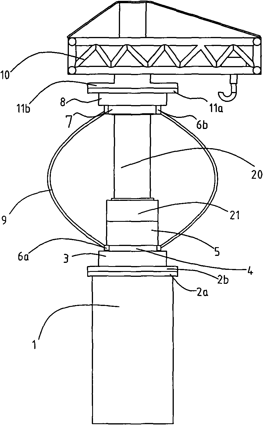
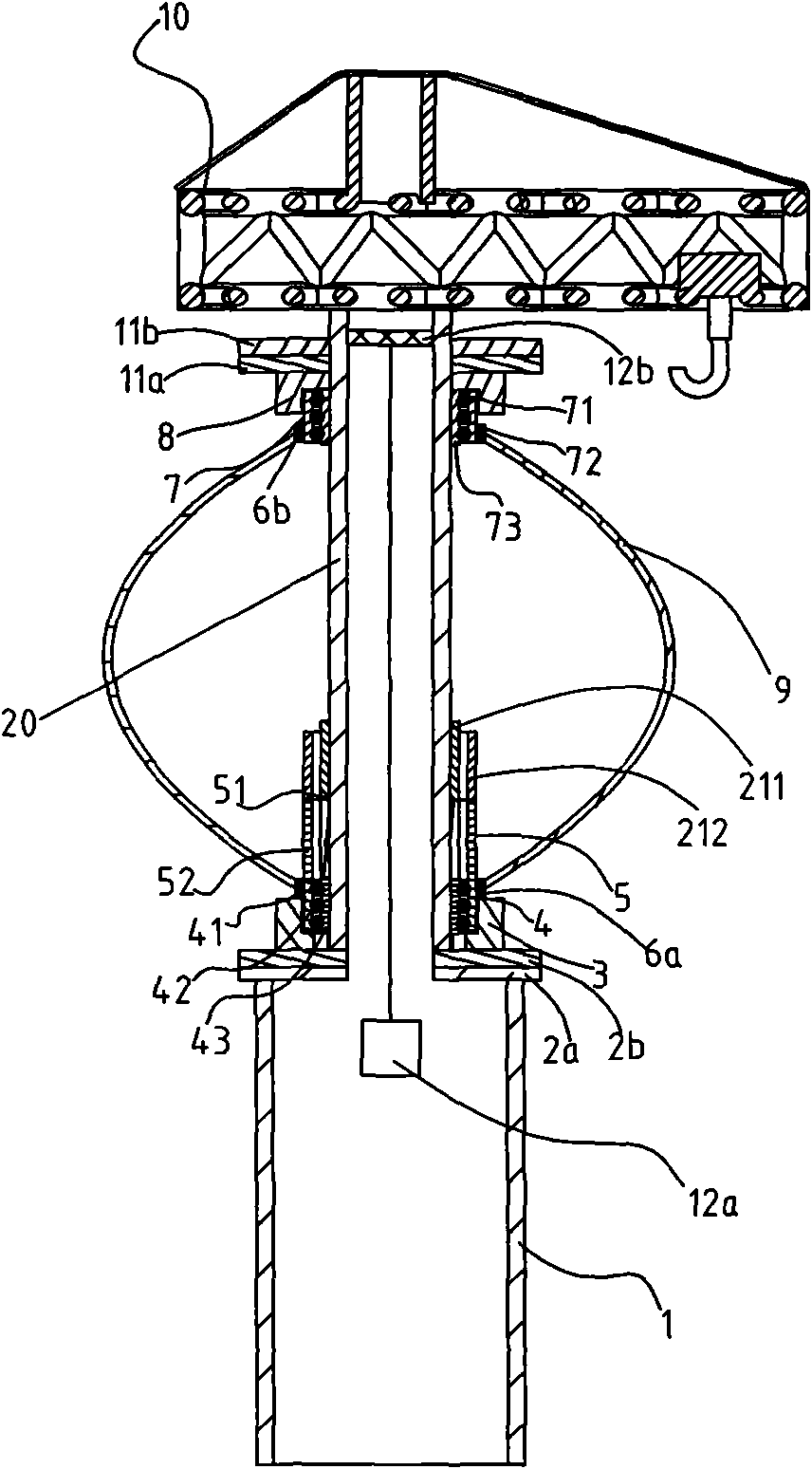
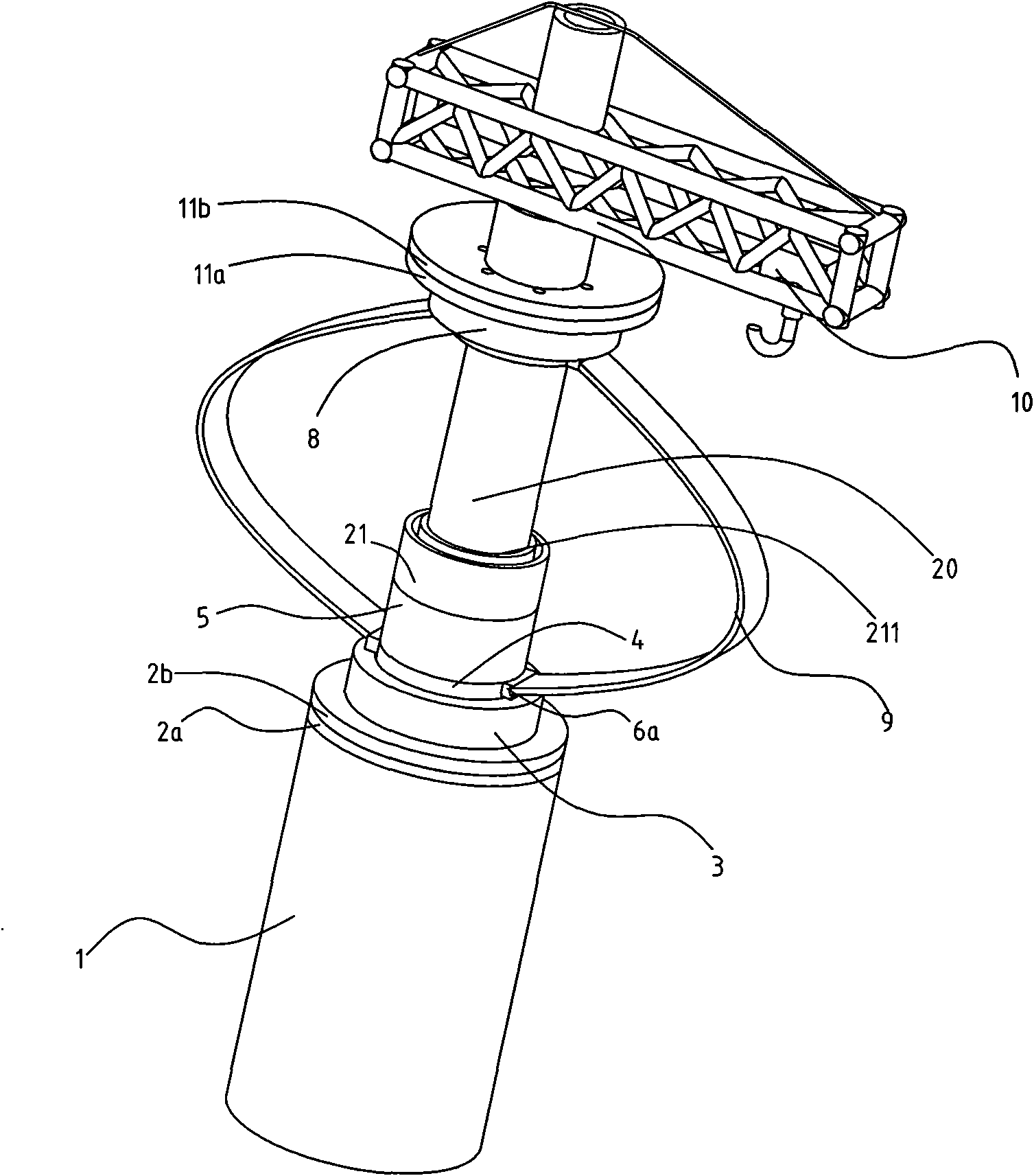
[0037] Such as Figures 1 to 3As shown, a vertical wind power generator includes a tower column 1 , a generator and two blades 9 . The tower column 1 is hollow, and a power generation device is arranged on the tower column 1 . The power generating device is composed of the first lower flange 2a and the first upper flange 2b, the first bearing seat 3, the first bearing 4, the first generator 5, and the generator center column 20 arranged on the tower column 1. , The second bearing 7, the second bearing seat 8, the second lower flange 11a and the second upper flange 11b. The first lower flange 2a is fixed to the tower column 1, the first upper flange 2b is located on the first lower flange 2a and is fixedly connected with the first lower flange 2a, the first The bearing seat 3 is fixed on the first upper flange 2b, the first bearing 4 is composed of a first outer ring 41, a first steel ball set 42 and a first inner ring 43, and the first inner ring 43 is fixed on the second O...
Embodiment 2
[0042] Such as Figures 4 to 6 As shown, a vertical wind power generator includes a tower 1, a generator and two blades 9; the tower 1 is hollow, and a power generation device is arranged on the tower 1. The power generating device is composed of the first lower flange 2a and the first upper flange 2b, the first bearing seat 3, the first bearing 4, the first generator 5, and the generator center column 20 arranged on the tower column 1. , the second bearing 7, the second bearing seat 8, the second lower flange 11a and the second upper flange 11b; the first lower flange 2a is fixed to the tower column 1, and the first upper The flange 2b is located on the first lower flange 2a and is fixedly connected with the first lower flange 2a, the first bearing seat 3 is fixed on the first upper flange 2b, and the first bearing 4 is formed by The first outer ring 41, the first steel ball group 42 and the first inner ring 43 are formed. The first inner ring 43 is fixed on the first bearin...
Embodiment 3
[0046] Such as Figures 9 to 10As shown, the difference from Embodiment 2 is that two power generating devices are arranged on the tower column 11, and the power generating device located on the lower floor includes a first lower flange 2a, a first upper flange 2b, a first bearing Seat 3, first bearing 4, first generator 5, first exciter 21, generator central column 20, second bearing 7, second bearing seat 8, second lower flange 11a and second upper flange and a second generator 13 including a second inner stator 131 , a second outer rotor 132 and a second exciter 22 is provided below the second bearing 7 . The power generation device on the upper floor is identical in structure to the power generation device on the lower floor. The power generation principle of the two power generation devices is the same as that of the power generation device described in Embodiment 2, and will not be described in detail here.
PUM
 Abstract
Description
Claims
Application Information
 - R&D
- Intellectual Property
- Life Sciences
- Materials
- Tech Scout
- Unparalleled Data Quality
- Higher Quality Content
- 60% Fewer Hallucinations
Browse by: Latest US Patents, China's latest patents, Technical Efficacy Thesaurus, Application Domain, Technology Topic, Popular Technical Reports.
© 2025 PatSnap. All rights reserved.Legal|Privacy policy|Modern Slavery Act Transparency Statement|Sitemap|About US| Contact US: help@patsnap.com


