Phase difference detection device and method for a position detector

a detection device and position detector technology, applied in the direction of instruments, data switching networks, electric controllers, etc., can solve the problems of increasing the number of detection-signal transmitting lines, directly appearing as detection errors, etc., to achieve superior high-speed response characteristics, simplify detection-signal transmission lines, and minimize adverse influences of external disturbances

Inactive Publication Date: 2005-04-26
AMITEQ
View PDF9 Cites 11 Cited by
  • Summary
  • Abstract
  • Description
  • Claims
  • Application Information

AI Technical Summary

Benefits of technology

[0010]It is therefore an object of the present invention to provide a phase difference detection device and method for use with a position detector which can perform a high-accuracy position detection without being influenced by unwanted phase variation caused by various factors, other than a position-to-be-detected, such as impedance change in a position sensor due to temperature change, which presents superior high-speed response characteristics, or which can significantly simplify detection-signal transmission lines and also minimize adverse influences of external disturbances, such as temperature changes, on the detection signal on the transmission lines.
[0015]The detected phase difference (θ), i.e., position detection data, is pulse-with-modulated via a pulse-width modulation circuit, to provide a pulse-width-modulated position detection signal having a pulse with corresponding to the phase difference (θ). The pulse-width-modulated position detection signal is then supplied via transmission wirings or lines to another device utilizing the signal (hereinafter called a “utilizing device”). Transmission of the detected position data in the form of the pulse-width-modulated position detection signal is advantageous in that it can simplify the transmission wirings or lines and prevent voltage level variations of the signal, due to various adverse influences on the signal passing through the wirings such as impedance variations by the influence of wiring capacity, noise and temperature changes, from causing errors to the position detection signal, thereby constantly guaranteeing a high detection accuracy.
[0016]Consequently, the present invention permits a high-accuracy position detection without being influenced by various factors, other than the position-to-be-detected, such as impedance change of the sensor due to temperature change and ununiform lengths of wiring cables. Further, because the present invention is based on the technique of measuring a phase difference (θ) in A.C. signals, the instant latching method may be employed rather than the conventional successive incrementing method, and thus the invention can achieve a phase difference detection device or method which presents superior high-speed characteristics. In addition, by transmitting the detected position data in the form of the pulse-width-modulated position detection signal as mentioned above, there is achieved the superior benefit that the transmission wirings or lines can be significantly simplified and various adverse influences on the signal passing through the wirings can be reliably avoided.

Problems solved by technology

However, the resolvers of this type are disadvantageous in that they require brushes for electric contact with the primary winding on the rotor.
Additionally, the electric phase of the induced A.C. signals received by a detection circuit varies under the influence of various factors other than a position-to-be-detected, such as ununiform wiring lengths between the windings of the sensor and the detection circuit and delays in various circuit operations.
On the other hand, in the latter-type detection system, the phase variation amount “±d” based on the non-positional factors (other than the position-to-be-detected) such as temperature change presents a very significant problem that the variation “±d” directly appears as a detection error.
The scheme of generating phase detection data in digital representation permits a high-accuracy detection, but is disadvantageous in that it would require an increased number of detection-signal transmitting lines if the digital detection data are transmitted directly in a parallel fashion.

Method used


Image

  • Phase difference detection device and method for a position detector
  • Phase difference detection device and method for a position detector
  • Phase difference detection device and method for a position detector

Examples


Embodiment Construction

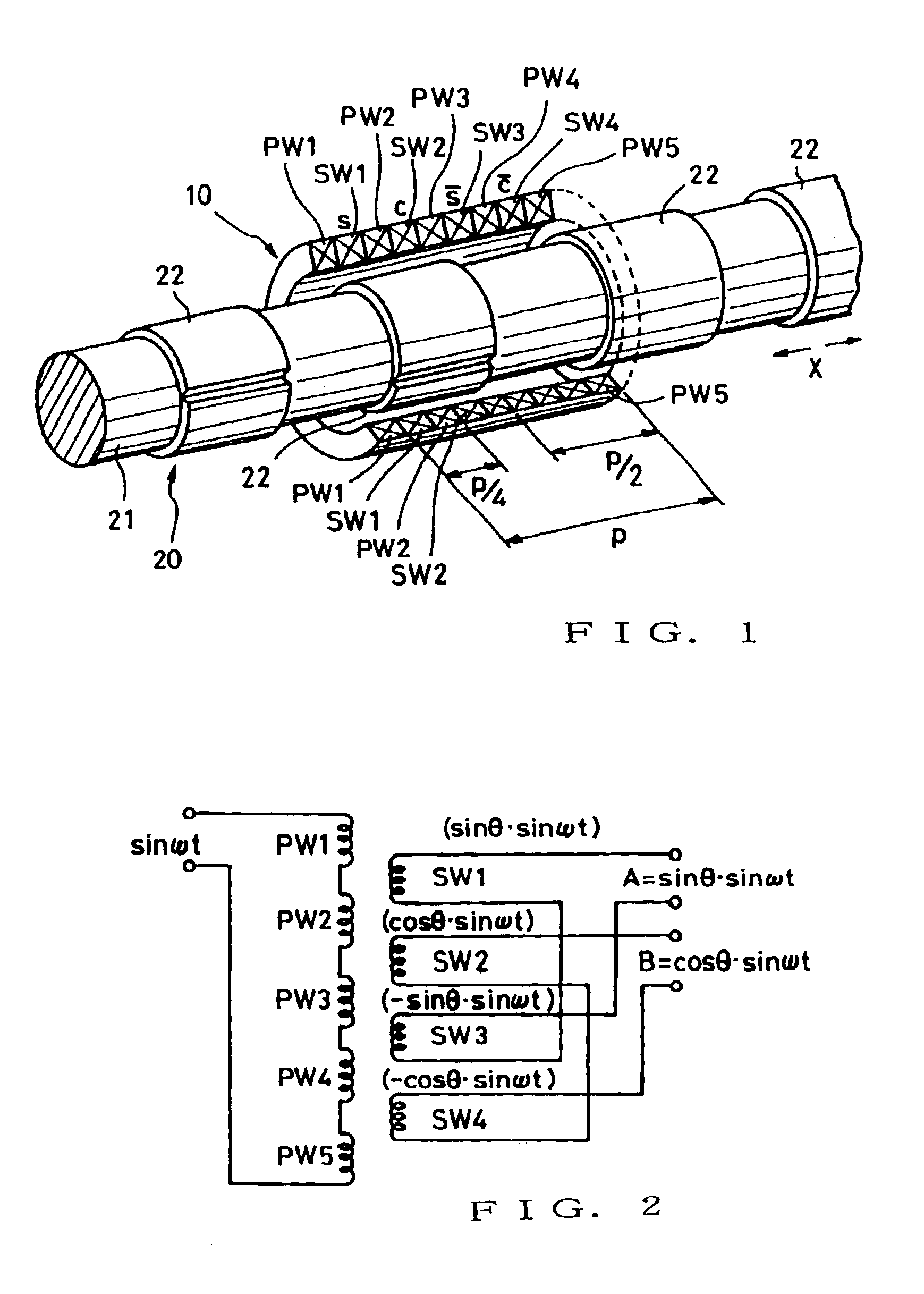
[0040]FIG. 1 is a perspective view of an example of a linear position detector device which is applicable to a phase difference detection device according to the present invention. The linear position detector device generally comprises a winding section 10 and a variable magnetic coupling section 20. The variable magnetic coupling section 20, which is coupled to a predetermined mechanical system (not shown) that is an object of detection by the detector device, is capable of linearly reciprocating in response to a varying linear position of the mechanical system. On the other hand, the winding section 10 is positionally fixed in a suitable manner. Thus, the variable magnetic coupling section 20 linearly moves relative to the winding section 10, in response to a varying linear position of the mechanical system to be detected (object of detection). Conversely, the winding section 10 may be constructed to move in response to a varying linear position of the mechanical system to be det...


PUM


Abstract

Two A.C. output signals amplitude-modulated in accordance with two function values (sine and cosine) differing from each other in correspondence to a position-to-be-detected are received from a position sensor such as a resolver. By performing an addition or subtraction between a signal derived by shifting the electric phase of one of the received A.C. output signals by a predetermined angle, and the other received signal, two electric A.C. signals (sin(ωt±d+θ), sin((ωt±d−θ)) are electrically synthesized which have electric phase angles (θ) corresponding to the position-to-be-detected and are phase-shifted in opposite directions. “±d” here represents phase variation error caused by factors, other than the position-to-be-detected, such as temperature change. In the synthesized two signals, the phase variation errors (±d) appear in the same direction, while the phase differences (θ) corresponding to the position are shifted in opposite, positive and negative, directions. Thus, by measuring the respective phase shift amounts (±d+θ, ±d−θ) and performing appropriate operation, it is allowed to cancel out or extract the error (±d) so that an accurate phase difference (θ) can be detected. Position detection data indicative of the detected phase difference (θ) is converted into a pulse-width-modulated signal and transmitted in the pulse-width-modulated form.

Description

RELATED APPLICATIONS[0001]This application is a continuation of U.S. application Ser. No. 09 / 479,605, filed on Jan. 6, 2000, now U.S. Pat. No. 6,552,666, which in turn is a continuation-in-part application of U.S. application Ser. No. 08 / 818,974 filed Mar. 14, 1997, now U.S. Pat. No. 6,034,624.BACKGROUND OF THE INVENTION[0002]The present invention relates to a phase difference detection device and method for use in position detection and a position detection system which are applicable to detection of both rotational positions and linear positions, such as a rotational position detector like a resolver or synchro, or a linear position detector based on a similar position detecting principle. More particularly, the present invention relates to a technique to detect an absolute position on the basis of an electric phase difference.[0003]Among various induction-type rotational position detectors, one which produces two-phase (sine phase and cosine phase) outputs in response to a single...

Claims


Application Information

Patent Timeline
Patent Type & Authority Patents(United States)
IPC IPC(8): G01B7/02G01D5/22G01D5/12H04L12/56H04L12/28H02H1/00H04L29/06
CPCG01B7/02G01D5/2216H04L12/5692H04L69/08H02H1/0061
Inventor GOTO, ATSUTOSHIYUASA, YASUHIROTANAKA, SHUICHIAKATSU, NOBUYUKISAKAMOTO, KAZUYASAKAMOTO, HIROSHIYAMAMOTO, AKIO
Owner AMITEQ
Why Eureka
Try Eureka