Nozzle and nozzle head

a technology of nozzles and nozzle heads, applied in the field of nozzles, can solve the problems of complicated nozzle heads, large nozzle heads, and inability to provide compact and effective constructions of industrial scale apparatuses, and achieve the effect of simple structur

Inactive Publication Date: 2015-01-01
BENEQ OY
View PDF6 Cites 189 Cited by
  • Summary
  • Abstract
  • Description
  • Claims
  • Application Information

AI Technical Summary

Benefits of technology

[0008]An advantage of the nozzle and nozzle head of the present invention is a compact structure in which the discharge channel and the precursor supply channel are nested. This eliminates the need for separate discharge channels and precursor supply channels. Furthermore, a single discharge channel is arranged to form a discharge sub-channel on both sides of the precursor supply channel instead of two separate discharge channels. Therefore, the nozzle and nozzle head is simpler in structure and more compact. This means that a larger number of precursor supply channels may be formed on a certain surface area of the output face of the nozzle head and further growth layers may be produces on the substrate surface with one scan.

Problems solved by technology

The problem with this prior art nozzle head is that it comprises several different nozzles and channels which makes the nozzle head complicated and rather large.
The prior art nozzles and nozzle heads do not provide compact and effective constructions for industrial scale apparatuses.

Method used


Image

  • Nozzle and nozzle head
  • Nozzle and nozzle head
  • Nozzle and nozzle head

Examples


Embodiment Construction

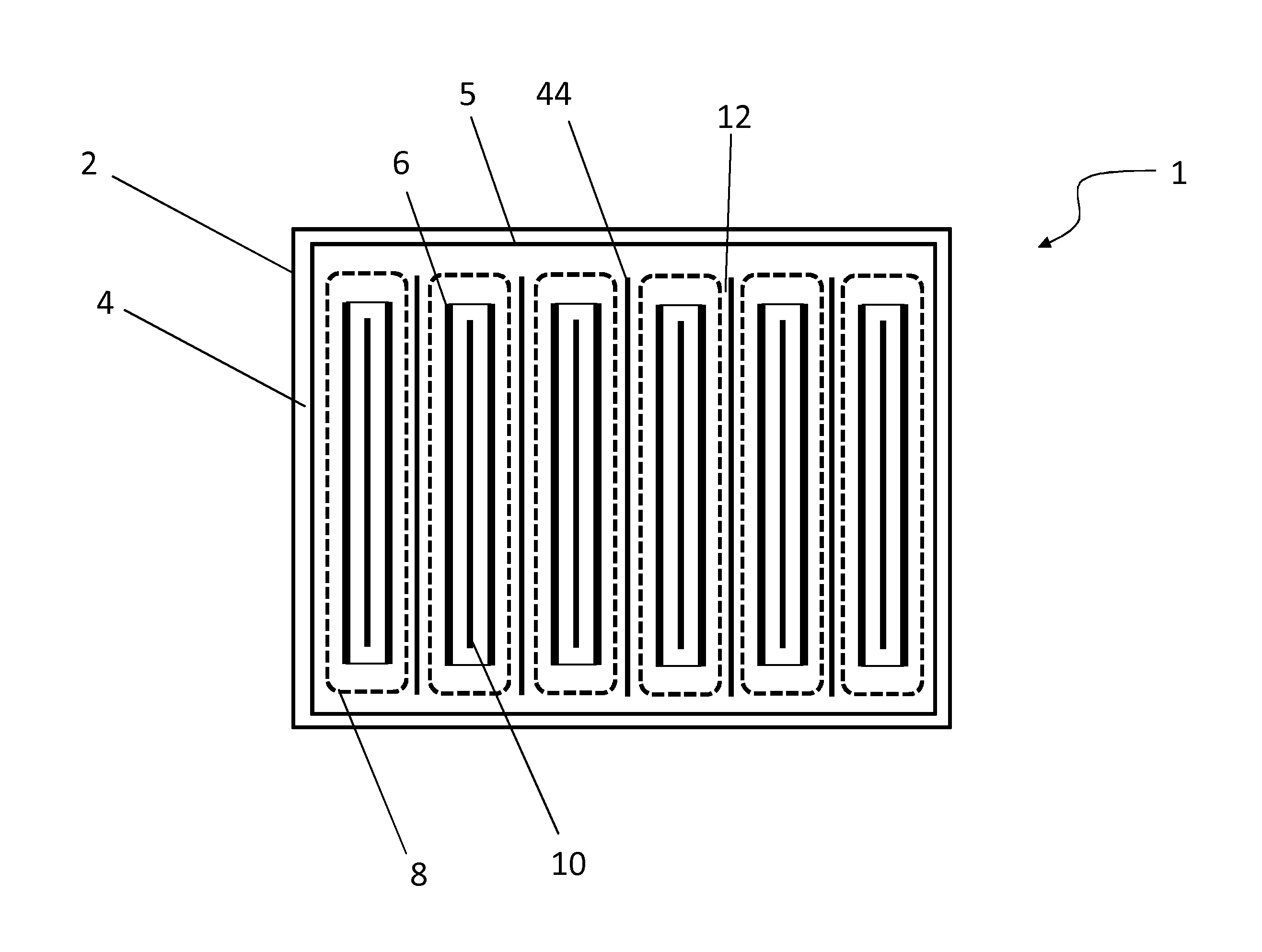
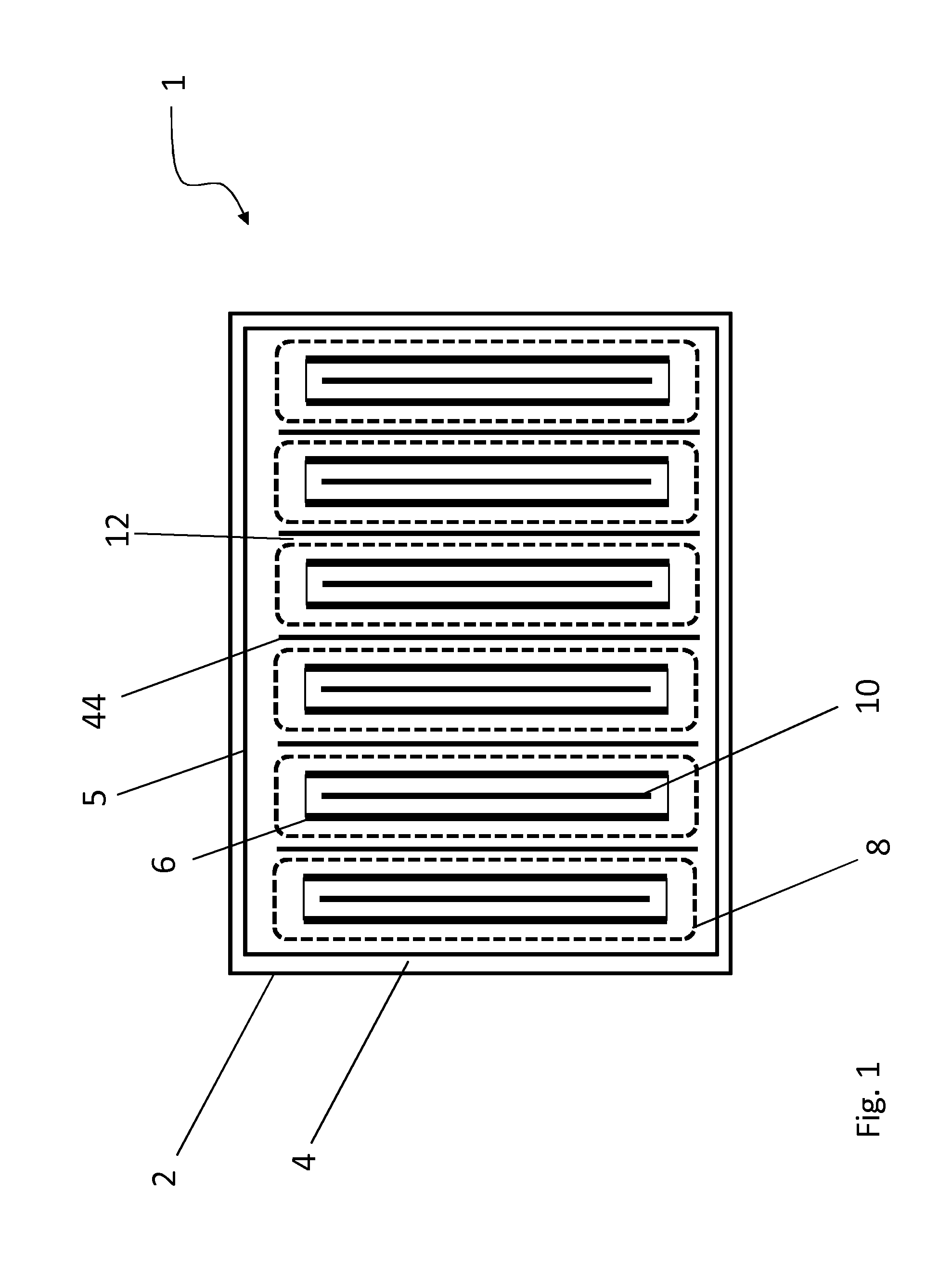
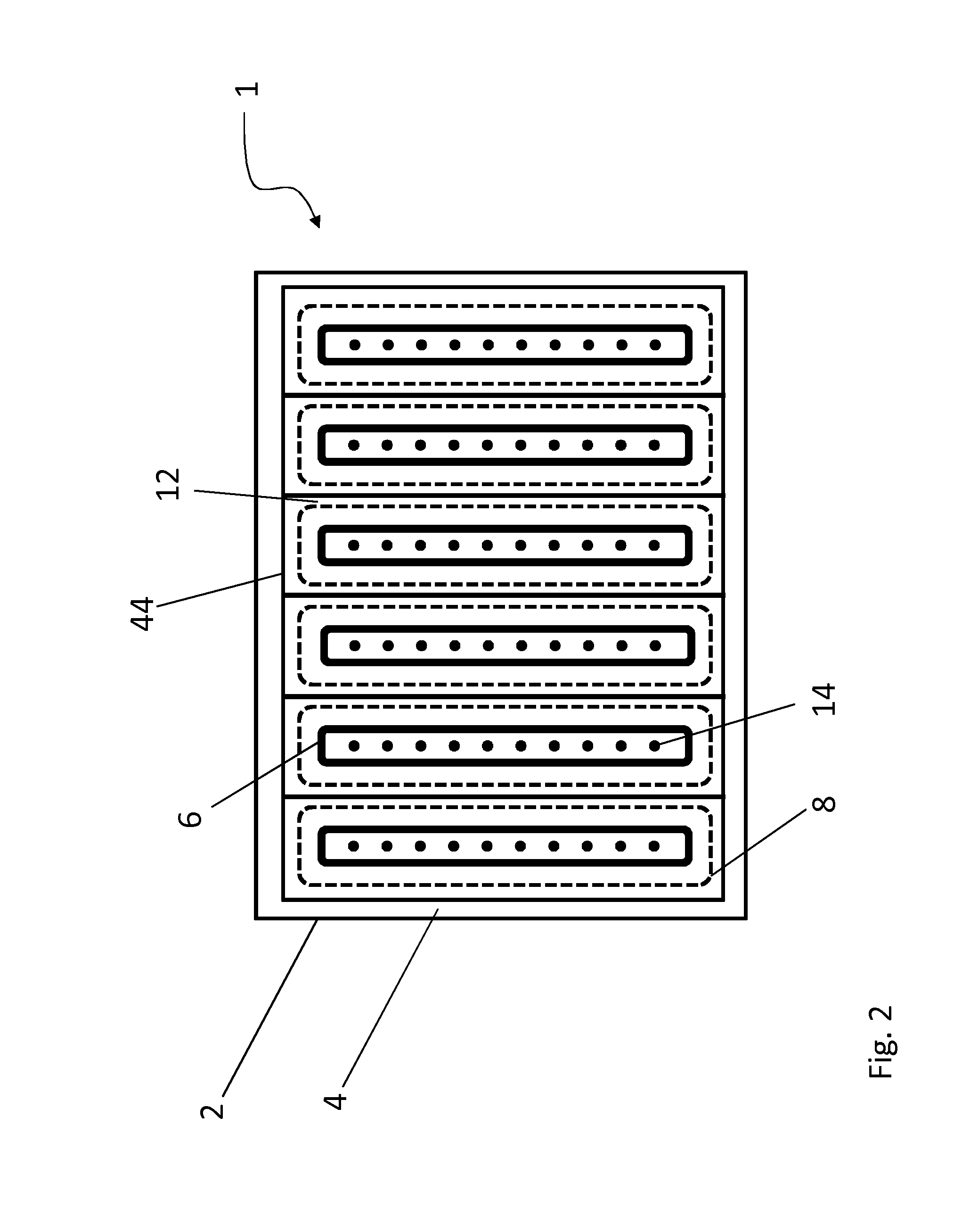
[0019]FIG. 1 shows schematically one embodiment of a nozzle head 1 according to the present. The nozzle head 1 comprises nozzle head body 2 and a nozzle head output face 4 via which the gaseous precursors are supplied. In the embodiment of FIG. 1 the nozzle head output face 4 is planar, but in an alternative embodiment it may also be non-planar, curved, cylindrical or have any other suitable form. The nozzle head 1 is provided with nozzles 8 arranged adjacently to each other and extending longitudinally along the output face 4. The nozzles 8 are shown with dashed lines in FIGS. 1 and 2. The nozzles 8 are separated with a distance or gap 12 from each other. The nozzles 8 comprise a discharge channel 6 and a precursor supply channel 10 arranged inside the discharge channel 6. In this embodiment the discharge channel 6 and the precursor supply channel 10 are formed as longitudinal channels. As shown in FIG. 1 the precursor supply channel 10 divides the discharge channel 6 into two disc...


PUM

PropertyMeasurementUnit
widthaaaaaaaaaa
discharge perimeteraaaaaaaaaa
surface reactionaaaaaaaaaa

Abstract

A nozzle and nozzle head arranged to subject a surface of a substrate to gaseous precursors. The nozzle includes an output face via which the precursor is supplied, a longitudinal precursor supply element for supplying precursor and a longitudinal discharge channel open to and along the output face for discharging at least a fraction of the precursor supplied from the precursor channel. The precursor supply element is arranged to extend inside the discharge channel such that the precursor supply element divides the discharge channel in the longitudinal direction to a first discharge sub-channel and a second discharge sub-channel on opposite sides of the precursor supply element for supplying precursor through the discharge channel.

Description

FIELD OF THE INVENTION[0001]The present invention relates to a nozzle for subjecting a surface of a substrate to a gaseous precursor and particularly to a nozzle head according to the preamble of claim 1. The present invention further relates to a nozzle head for subjecting a surface of a substrate to successive surface reactions of at least a first precursor and a second precursor, and particularly to a nozzle head according to the preamble of claim 16.BACKGROUND OF THE INVENTION[0002]In the prior art several types of apparatuses, nozzle heads and nozzles are used for subjecting a surface of a substrate to successive surface reactions of at least a first precursor and a second precursor according to the principles of atomic layer deposition method (ALD). In ALD applications, typically two gaseous precursors are introduced into the ALD reactor in separate stages. The gaseous precursors effectively react with the substrate surface, resulting in deposition of a growth layer. The precu...

Claims


Application Information

Patent Timeline
Patent Type & Authority Applications(United States)
IPC IPC(8): C23C16/455C23C16/44
CPCC23C16/4412C23C16/45574C23C16/45544C23C16/45578C23C16/45548B05B13/0278H01J37/32
Inventor ALASAARELA, TAPANISOININEN, PEKKAJAUHIAINEN, MIKA
Owner BENEQ OY
Why Eureka
Try Eureka