Device for controlling automatic transmission

Active Publication Date: 2015-01-01
JATCO LTD +1
View PDF3 Cites 0 Cited by
  • Summary
  • Abstract
  • Description
  • Claims
  • Application Information

AI Technical Summary

Benefits of technology

[0012]Specifically, in the gear shift from the first gear shift stage to the second gear shift stage, the first frictional engagement element to be engaged at the first gear shift stage and to be released at the second gear shift stage is controlled to change from an engaged state thereof to a released state thereof. On the other hand, in the gear shift from the second gear shift stage to the first gear shift stage (that is, in the gear shift control to return the gear shift stage to the initial gear shift stage), the first frictional engagement element is controlled to change from the released state thereof to the engaged state thereof. However, when the gear shift from the first gear shift stage to the second gear shift stage is finished, variation occurs in the released state of the piston that is actuated to press the friction discs of the first frictional engagement element. Therefore, by executing the gear shift from the seco

Problems solved by technology

However, in the above conventional device for controlling an automatic transmission, after the inertia phase is once started, the change of the target gear shift stage is prohibited, but it is not clearly shown at what time the gear shift control to return the gear shift stage should be initiated after the gear shift control is finished.
On the contrary, when the gear shift control to return the gear shift stage

Method used


Image

  • Device for controlling automatic transmission
  • Device for controlling automatic transmission
  • Device for controlling automatic transmission

Examples


Example

[0018]In the following, a device for controlling an automatic transmission according to an embodiment of the present invention is explained with reference to the accompanying drawings.

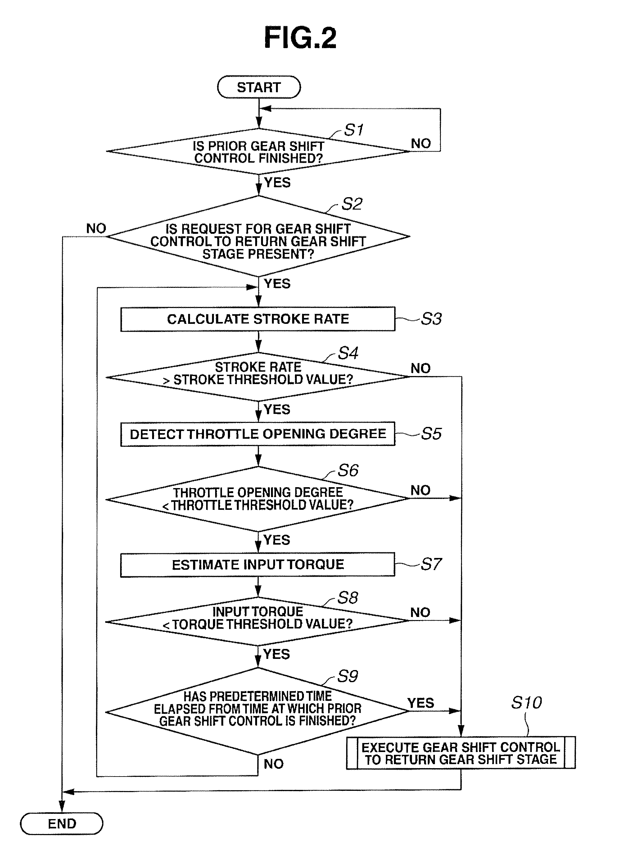
[0019]A configuration of the device for controlling an automatic transmission according to the embodiment is classified into “General System Configuration” and “Configuration of Gear Shift Start Determination Process”, which are separately explained below.

[0020][General System Configuration]

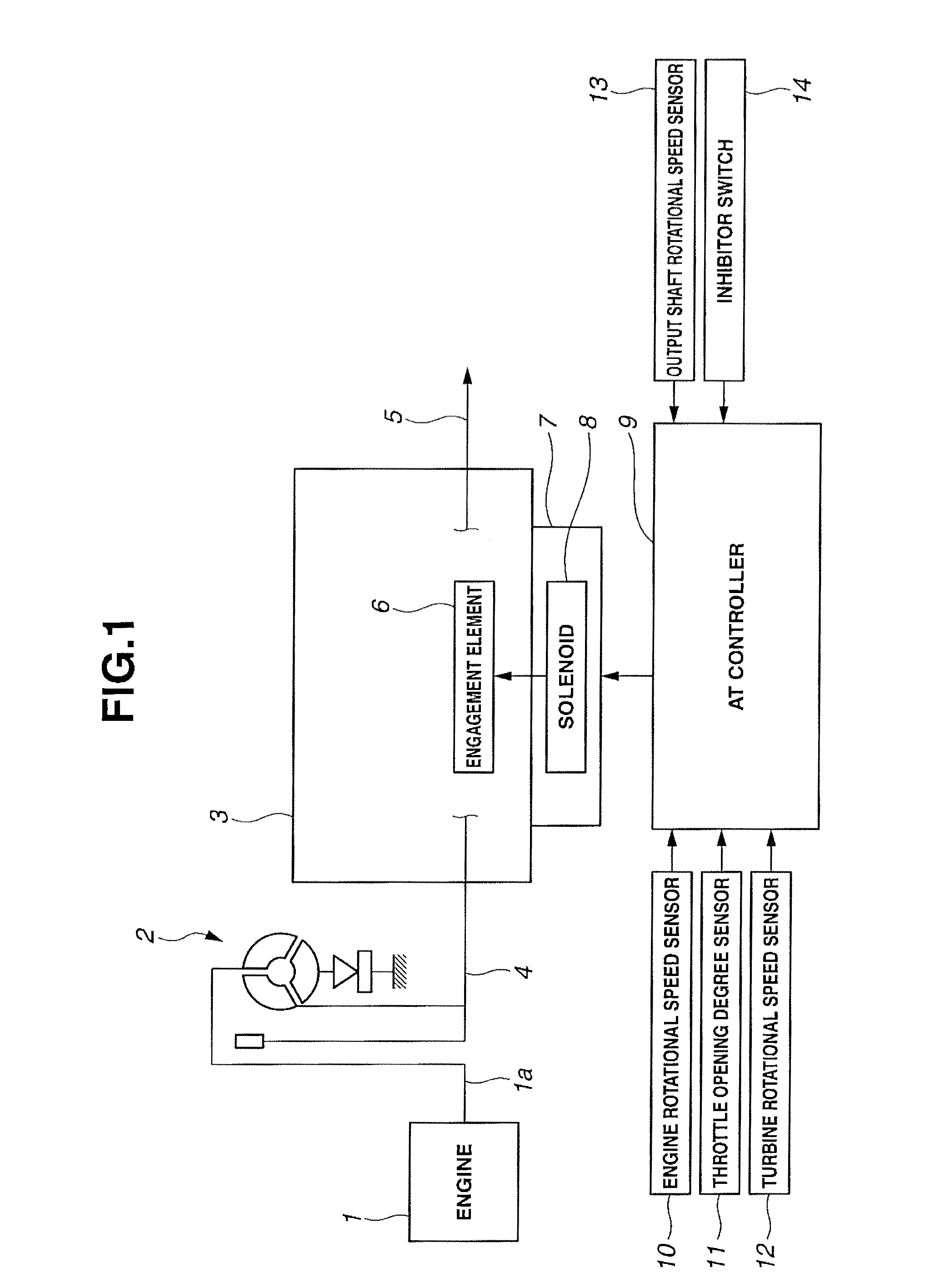
[0021]FIG. 1 is a general system diagram showing a configuration of a power train of a vehicle to which the device for controlling an automatic transmission according to the embodiment is applied.

[0022]As shown in FIG. 1, the power train of the vehicle in the embodiment includes engine 1, torque converter 2, and automatic transmission 3.

[0023]Engine 1 may be a gasoline engine or a diesel engine, and an output of engine 1 is varied by a throttle valve that is operated in association with an accelerator pedal operated...


PUM


Abstract

A device for controlling an automatic transmission including a first frictional engagement element that is engaged at a first gear shift stage and is released at a second gear shift stage, the device including a piston stroke return determination means for determining a released state of a piston that is actuated to press friction discs of the first frictional engagement element, and a gear shift start determination means for restricting execution of a gear shift from the second gear shift stage to the first gear shift stage until it is determined that the piston is in a predetermined released state after a gear shift from the first gear shift stage to the second gear shift stage is finished.

Description

TECHNICAL FIELD[0001]The present invention relates to a device for controlling an automatic transmission including frictional engagement elements each being controlled from an engaged state to a released state by gear shift control.BACKGROUND ART[0002]In recent years, a multi-stage configuration of an automatic transmission progresses so that the number of frictional engagement elements such as a clutch and a brake is increased in accordance with increase in number of gear shift stages. Further, intervals between gear shift lines in a gear shift map become significantly dense in accordance with the increase in number of gear shift stages, whereby a gear shift will readily occur due to a slight change in driving condition (for instance, a throttle opening degree, etc.). That is, gear shift frequency increases, so that a phenomenon in which a request for changing a target gear shift stage is present even during the gear shift more often occurs.[0003]There is conventionally known a dev...

Claims


Application Information

Patent Timeline
IPC IPC(8): B60K20/02F16H61/02F16H61/68
CPCF16H61/0265B60K20/14F16H61/68F16H61/08F16H59/74F16H61/061F16H61/686F16H2059/6807F16H2306/24F16H59/045
Inventor ENDO, GO
Owner JATCO LTD
Why Eureka
Try Eureka