Drive center with guard

a technology of safety guards and drive centers, which is applied in the direction of tailstocks/centres, turning machine accessories, manufacturing tools, etc., can solve the problems of difficult to force the center point, inability to impart the required torque, and the density of the material of different workpieces can vary, so as to achieve easy replacement, easy stop, and quick removal for resharpening

Active Publication Date: 2015-01-08
BIG TREE TOOLS
View PDF21 Cites 14 Cited by
  • Summary
  • Abstract
  • Description
  • Claims
  • Application Information

AI Technical Summary

Benefits of technology

[0012]A further objective of the present invention is to provide a spring loaded drive center that functions like a clutch so as to permit the workpiece to be easily stopped for measurement or inspection of the surface quality, such as during a sanding operation, without having to stop the spindle or motor.
[0013]Yet another objective of the present invention is to provide a drive center that is designed to allow the workpiece to be turned with the minimum of force from the tailstock. To accomplish this, the drive center, according to the invention, includes two pertinent features: First, the center point is provided with an adjustable spring that positions the point in a forward most orientation for initial location of the workpiece, but recedes out of the way as the workpiece is gradually advanced toward the spurs, thus causing minimal interference by the center point with the engagement of the spurs into the workpiece; and Second, the spurs are extremely sharp allowing them to embed and engage adequately with the workpiece and impart the necessary torque for the turning process.
[0014]Another objective of the present invention is to provide a drive center with spurs that can be quickly removed for resharpening, and following replacement, each of the spurs can be “micro adjusted” in the drive center so each of the spurs are the same length. Further, if a “two spur” center is desired, for roughing of cross grain bowls for example, two of the four spurs can be removed. The spurs of this drive center are also easily replaceable in the event that they become too short, from repeated sharpening, or possibly damaged by dropping or collision with another object.
[0015]A still further objective of the present invention is to provide a drive center having a guard which functions to enshroud or enclose the spurs thereby preventing objects, such as loose clothing, jewelry, or hair from inadvertently becoming entangled with the spurs, and preventing any part of the operator's body from coming into contact with the spurs. Because the guard itself is not rotationally fixed, it will stop rotating if the guard becomes entangled with clothing, jewelry, or hair.

Problems solved by technology

There are a number of drawbacks associated with known drive centers.
One of the encountered problems stems from the fact that the density of the material of different workpieces can vary greatly.
If the material is very dense, it is difficult to force the center point far enough into the workpiece so that the spurs will sufficiently engage with the workpiece.
In this case, spurs are unable to impart the required torque and tend to slip against the workpiece.
It is known that the increase of force, between the centers, creates an excessive load on the headstock bearings and revolving center which results in premature wear and possible failure of the lathe.
Further, the workpiece tends to deflect or flex from the centerline when it is “squeezed” too tightly by the centers.
This flexing, sometimes called “whip,” leads to vibration of the workpiece and causes the chisel to “chatter” which creates marks on the workpiece which are undesirable and difficult to repair.
The workpiece often becomes eccentric when it is removed from the lathe and then not accurately re-centered when it is again remounted on the lathe.
Although some of the known drive centers may have spring loaded center points and adjustable spurs, a major drawback of the known drive centers lies in the fact that the spurs are exposed, thus creating a safety hazard.
Due to the high rate of rotation of the drive centers and the power imparted by the machine, when something becomes entangled with the spurs, this often results in serious injury to the turner.
Further, a collision between the tool rest or a chisel and the drive center can cause injury to the turner and damage to the spur center.

Method used


Image

  • Drive center with guard
  • Drive center with guard
  • Drive center with guard

Examples


Embodiment Construction

[0038]The present invention will be understood by reference to the following detailed description, which should be read in conjunction with the appended drawings. It is to be appreciated that the following detailed description of various embodiments is by way of example only and is not meant to limit, in any way, the scope of the present invention.

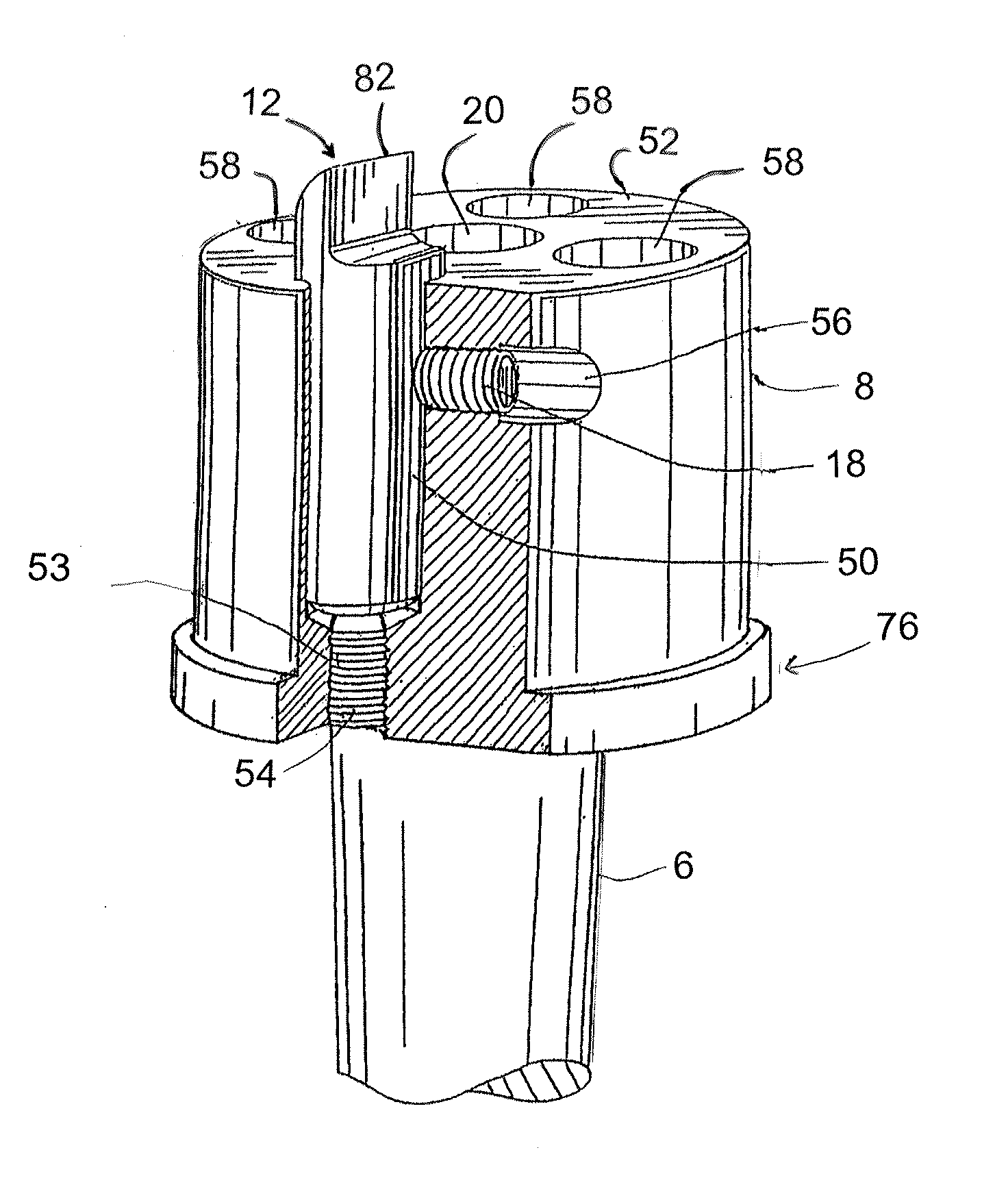
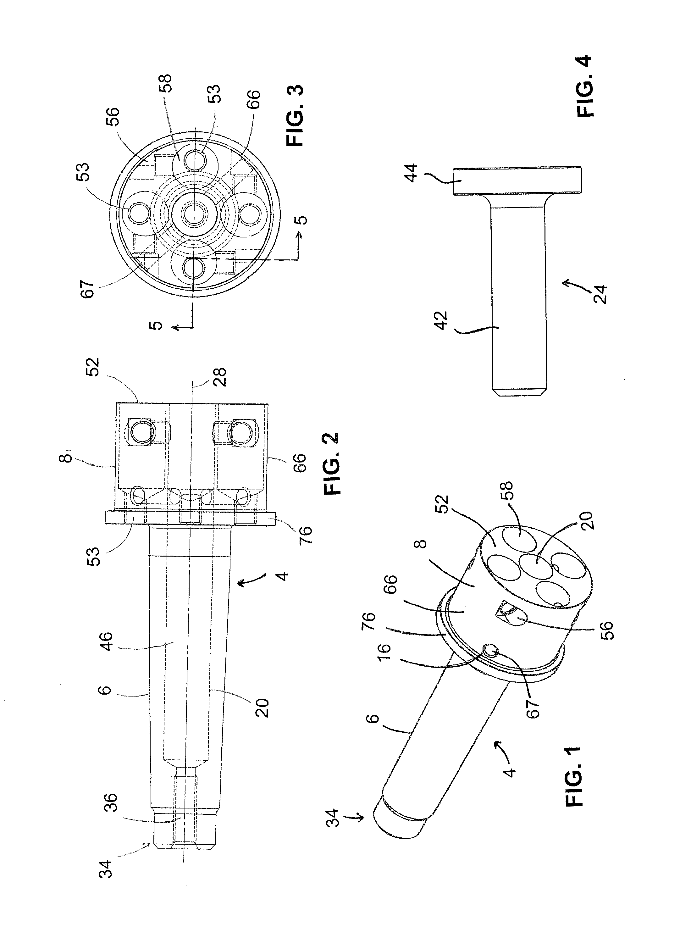
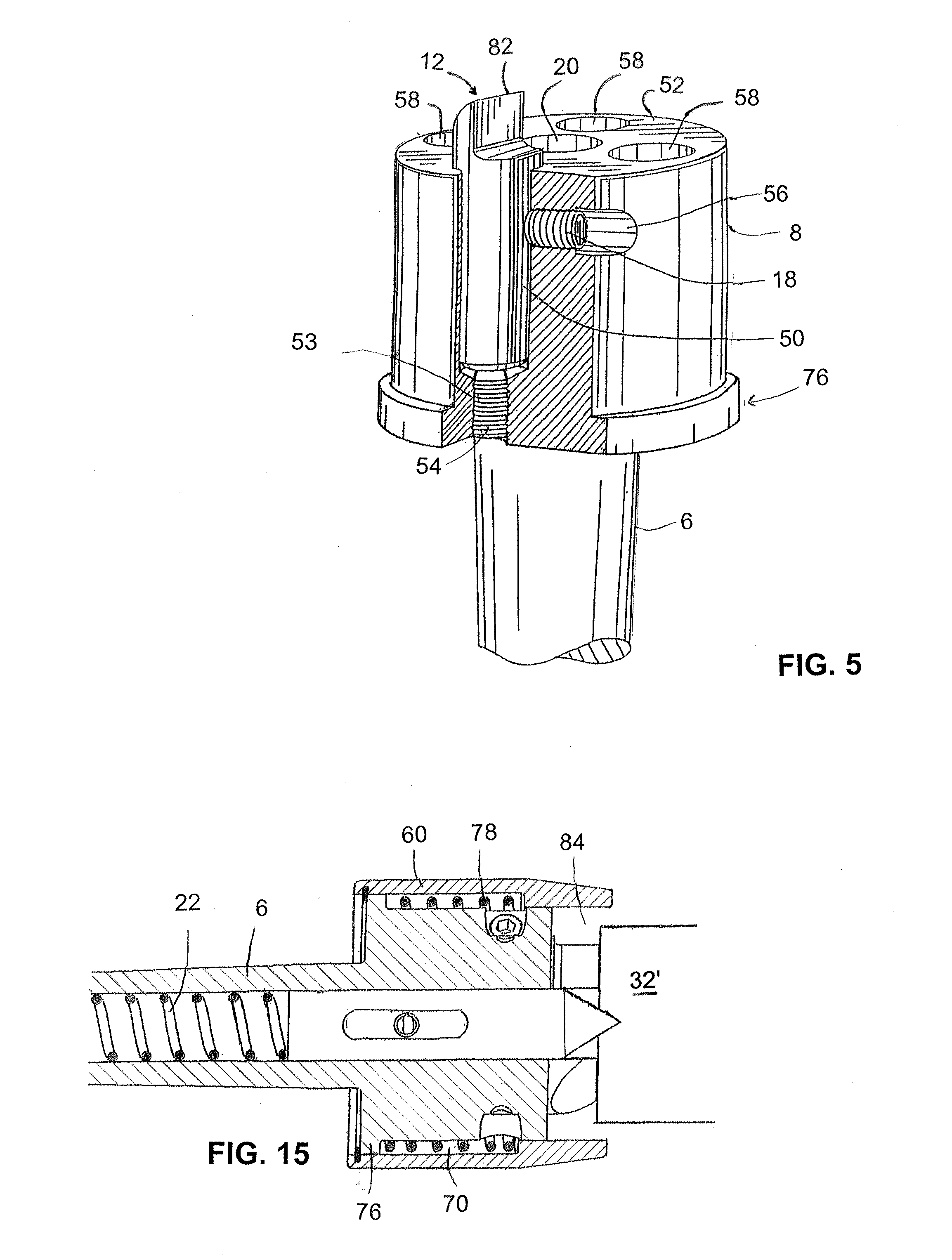
[0039]Turning now to FIGS. 1-9, the various components of the drive center 2, according to present invention, will now be briefly discussed. As can be seen, the drive center 2 comprises a body 4 that includes a shank 6 and head 8. The shank 6 is an elongate member that is tapered to fit into the tapered bore of the headstock spindle 10 of a lathe (FIG. 16). The head 8 of the body 4 comprises a plurality of apertures 56, 58, 67 and 20. Apertures 58 receive and support a number of spurs 12, e.g., typically four, a center point 14, a retaining pin 16, set screws 18 and adjusting screws 54 which are utilized to adjust and lock the position of ...


PUM


Abstract

A drive center constituting a machine tool accessory being used on a lathe for holding workpieces that are mounted between the headstock and the tailstock (between centers). The drive center comprises a head having an adjustable spring-loaded center point and a number of removable, adjustable spurs that are capable of penetrating a workpiece sufficiently to provide torque for the turning process. The head is attached to a shank with a standard taper to fit the spindle of a lathe. A cylindrical guard is supported coaxially by the external surface of the head so that the guard radially encircles the head and the spurs but is able to slide axially and rotationally with respect to the head. A spring causes the guard to extend axially beyond the spurs except when pushed back by the workpiece.

Description

FIELD OF THE INVENTION[0001]The present invention relates to an apparatus for holding a workpiece as the workpiece rotates in a lathe and, more specifically, to a highly adjustable drive center equipped with a safety guard.BACKGROUND OF THE INVENTION[0002]Holding devices used in conjunction with lathes for mounting a workpiece between the headstock and tailstock of the lathe, are typically called drive centers, spur centers, or prong centers. These devices are intended to serve both the function of accurately locating the workpiece and rotating the workpiece (i.e., driving it), such that the device maintains correct centering and continued rotation as the operator applies torque on the workpiece by means of cutting tools.[0003]Typical drive centers have a tapered shank that is received by an identically tapered bore in the spindle of the headstock of the lathe. Drive centers have a center point and a number of spurs or prongs. The spurs embed and engage in the workpiece and are reta...

Claims


Application Information

Patent Timeline
Patent Type & Authority Applications(United States)
IPC IPC(8): B23B23/04
CPCB23B2233/32B23B23/04B23B33/005B23B23/02B23B23/045B23B2233/24Y10T82/2568
Inventor SIEGEL, JONMORE, GRINNELL
Owner BIG TREE TOOLS
Why Eureka
Try Eureka