Controlling Sway of Elevator Rope Using Movement of Elevator Car

a technology of elevator car and elevator rope, which is applied in the direction of elevators, lifting devices, instruments, etc., can solve the problems of affecting the operation of the elevator system, affecting the safety of passengers, etc., and achieves the effect of reducing the sway of the elevator rop

Active Publication Date: 2015-01-08
MITSUBISHI ELECTRIC CORP +1
View PDF13 Cites 25 Cited by
  • Summary
  • Abstract
  • Description
  • Claims
  • Application Information

AI Technical Summary

Benefits of technology

[0009]It is an objective of some embodiments of an invention to provide a system and a method for reducing a sway of an elevator rope connected to an elevator car in an elevator system by changing the tension to the rope using a movement of the elevator car.
[0010]Some embodiments of this invention are based on a general realization that the elevator ropes tension can be modified based on the relative motion of the two extremity points of the ropes. Additionally or alternatively, some embodiments of this invention are based on a realization that vertical movement of the elevator car induces an extra tension in the ropes. This tension can be used to control the sway of the ropes. If the car vertical motion is properly controlled then the movement of the elevator car can be used to reduce the sway.
[0011]For example, in some embodiments, the movement of the elevator car is controlled by causing a main sheave of the elevator system to change a length of the elevator rope of the elevator car or a length of a rope supporting a counterweight of the elevator car. Thus, the sway of the elevator rope can be reduced with a minimal number of actuators or even without the usage of any actuators. Moreover, the movement of the elevator car can control the tension of a multitude of the elevator ropes simultaneously, without the need of any extra device to be added to the elevator system.
[0012]The control can be a periodic feedback control until, e.g., maximum amplitude of the sway is below a threshold. Some embodiments of the invention control the movement of the elevator car using a control law including a combination of a function of the state of the sway and a function of the state of the elevator car. Using the control law having such two components allows decoupling the movement of the car for reducing the sway, and the movement of the elevator car for stabilizing the elevator car around an initial position. Stabilizing the car around the initial position can minimize the effect of the sway on the elevator car and can create oscillation movement of the elevator car UP and DOWN around the initial position, which ensures a safety of the elevator system.
[0014]Some embodiments of the invention decouple the effect on the movement of the elevator car resulted from controlling according to the function of the state of the sway from the effect resulted from controlling according to the function of the state of the elevator car. For example, one embodiment determines the function of the state of the sway such that a frequency of the function of the state of the sway is proportional to a frequency of the sway. On the other hand, the embodiment determines the function of the state of the elevator car such that a frequency of the function of the state of the elevator car is different than the frequency of the function of the state of the sway. Such decoupling allows tuning the function to optimize the effect of the functions on both the reduction of the sway and the stability of the elevator car.

Problems solved by technology

The oscillation can be a significant problem in a roped elevator system.
If the elevator system uses multiple ropes and the ropes oscillate out of phase with one another, then the ropes can become tangled with each other and the elevator system may be damaged.
However, applying a constant tension to the rope is suboptimal, because the constant tension can cause unnecessary stress to the ropes.
However, that method only solves the problem of compensation rope vibration sway damping.
Furthermore, that method necessitates the measurement of the ropes sway velocity at the extremity of the rope, which is difficult in practical applications.
Furthermore, each damper is passive and engages continuously with the rope, which can induce unnecessary extra stress on the ropes.
Those types of solutions can be costly to install and maintain.

Method used


Image

  • Controlling Sway of Elevator Rope Using Movement of Elevator Car
  • Controlling Sway of Elevator Rope Using Movement of Elevator Car
  • Controlling Sway of Elevator Rope Using Movement of Elevator Car

Examples


Embodiment Construction

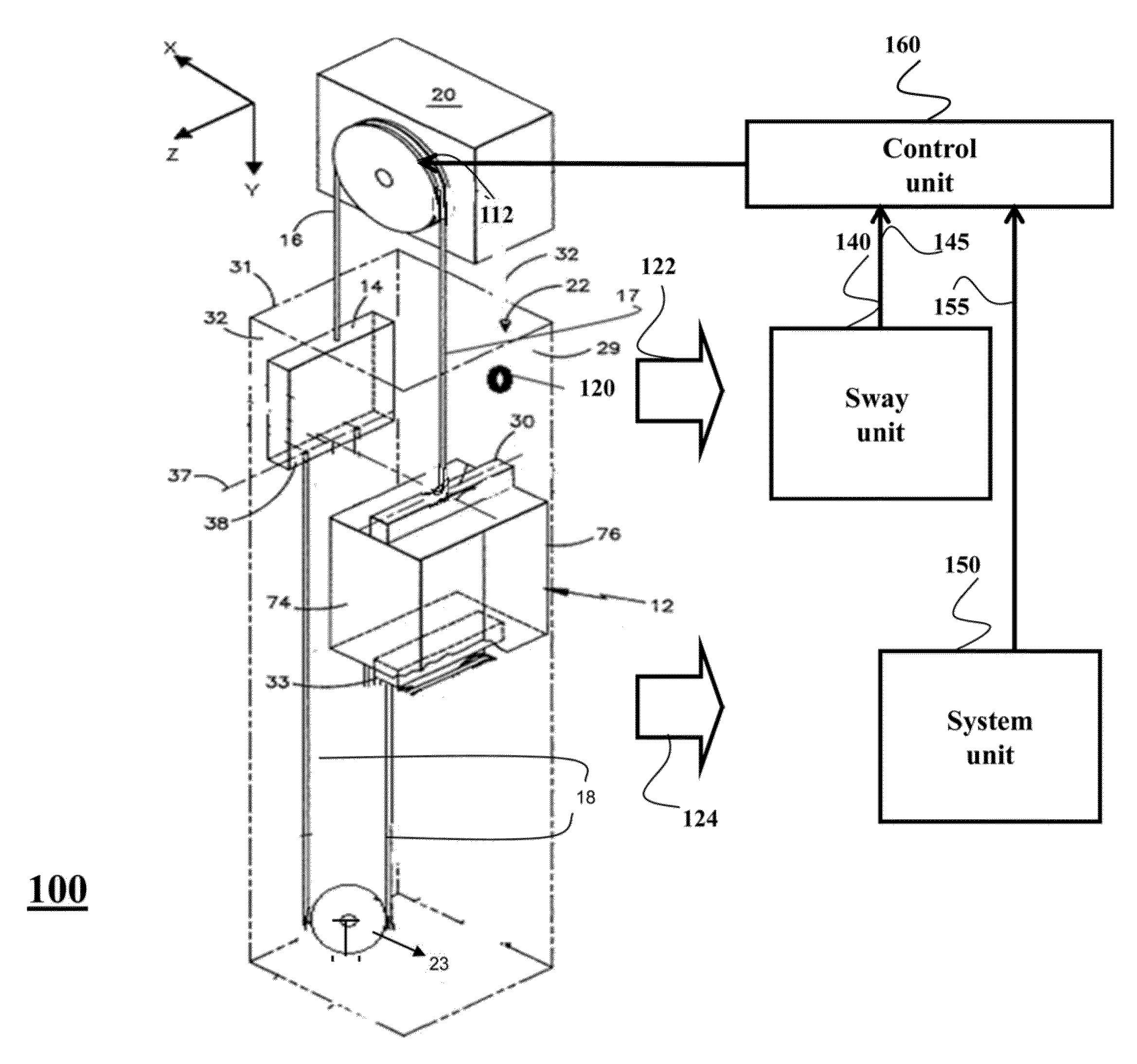
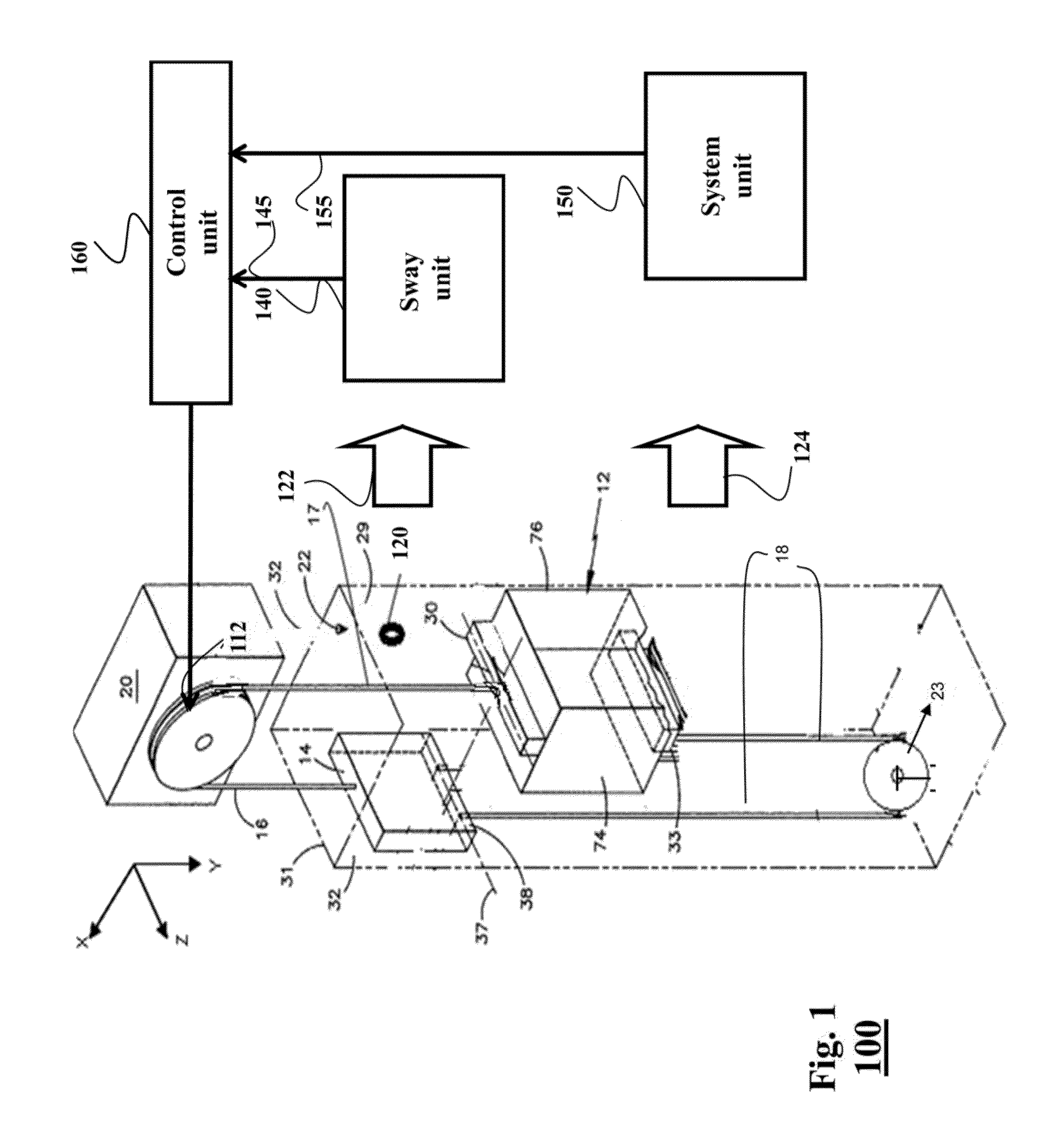
[0025]Various embodiments of the invention are based on a realization that tension applied to an elevator ropes can be used to reduce the sway of the ropes in an elevator system. Moreover, this tension can be obtained by controlling movement of the elevator car, e.g., a vertical movement within an elevator shaft, without the need of any extra actuators in the elevator system. For example, various embodiments control the main sheave to move the elevator car up and down around the initial static position, within a specified maximum car vertical motion amplitude, e.g. +3 m to −3 m, in such a way to induce enough tension on the elevator ropes and thus reduce the ropes sway.

[0026]FIG. 1 shows a schematic of an elevator system 100 according to one embodiment of an invention. The elevator system includes an elevator car 12 connected by at least one elevator rope to other components of the elevator system. For example, the elevator car and a counterweight 14 connect to one another by main r...


PUM


Abstract

A method reduces a sway of an elevator rope supporting an elevator car within an elevator system using an elevator sheave. The method controls, using a movement of the elevator sheave, a tension of the elevator rope according to a control law of the tension of the elevator rope between a first point and a second point. The first point is associated with a contact of the elevator rope with the elevator sheave. The second point is associated with a contact of the elevator rope with the elevator car or a counterweight of the elevator car. The control law is a function of one or combination of a relative position, a relative velocity and a relative acceleration between the first and the second points.

Description

FIELD OF THE INVENTION[0001]This invention relates generally to elevator systems, and more particularly to reducing a sway of an elevator rope in an elevator system using movement of the elevator car.BACKGROUND OF THE INVENTION[0002]Typical elevator systems include a car and a counterweight moving along guiderails in a vertical elevator shaft. The car and the counterweight are connected to each other by hoist ropes. The hoist ropes are wrapped around a sheave located in a machine room at the top or bottom of the elevator shaft. The sheave can be moved by an electrical motor, or the counterweight can be powered by a linear motor.[0003]Rope sway refers to oscillation of the hoist and / or compensation ropes in the elevator shaft. The oscillation can be a significant problem in a roped elevator system. The oscillation can be caused, for example, by vibration due to wind induced building deflection and / or the vibration of the ropes during operation of the elevator system. If the frequency...

Claims


Application Information

Patent Timeline
Patent Type & Authority Applications(United States)
IPC IPC(8): B66B5/02
CPCB66B5/02B66F7/06B66B7/06
Inventor BENOSMAN, MOUHACINEFUKUI, DAIKIWATANABE, SEIJINAKAZAWA, DAISUKE
Owner MITSUBISHI ELECTRIC CORP
Why Eureka
Try Eureka