Bus interface apparatus, router, and bus system including them

a bus system and bus interface technology, applied in the field of bus interface apparatus, routers, and bus systems including them, can solve the problems of inability bus system cannot in principle discard packets, and deterioration of transmission route performance, so as to improve buffer use efficiency, simplify the design process of semiconductor integrated circuits, and improve buffer use efficiency

Active Publication Date: 2015-01-08
PANASONIC INTELLECTUAL PROPERTY MANAGEMENT CO LTD
View PDF7 Cites 13 Cited by
  • Summary
  • Abstract
  • Description
  • Claims
  • Application Information

AI Technical Summary

Benefits of technology

[0013]The router according to an embodiment of the present disclosure recognizes the bus width on the bus master end, which is included as additional information in a packet, and can carry out appropriate addressing automatically by reference to the bus width in order to store a packet in an appropriate buffer and transmit the packet from the buffer. Thus, the buffer can be used more efficiently. As a result, there is no need to make settings for each individual router and the design process of a semiconductor integrated circuit can be simplified.
[0014]In addition, as the buffer use efficiency is increased, the throughput of the transmission route can also be increased. As a result, the bus' operating frequency and bus width can be reduced so much as to ensure good performance for a semiconductor integrated circuit, and this configuration would contribute to saving power and cutting down the chip area to use.

Problems solved by technology

However, if the space left in the buffer of the router that should store those packets ran short during the transfer, then the performance of the transmission route would deteriorate, which is a problem.
That is to say, such a bus system is not permitted in principle to discard packets.
That is why just by applying the conventional techniques such as the one disclosed in the JP Patent Publication to the routers, the buffer use efficiency cannot be improved.

Method used


Image

  • Bus interface apparatus, router, and bus system including them
  • Bus interface apparatus, router, and bus system including them
  • Bus interface apparatus, router, and bus system including them

Examples


Embodiment Construction

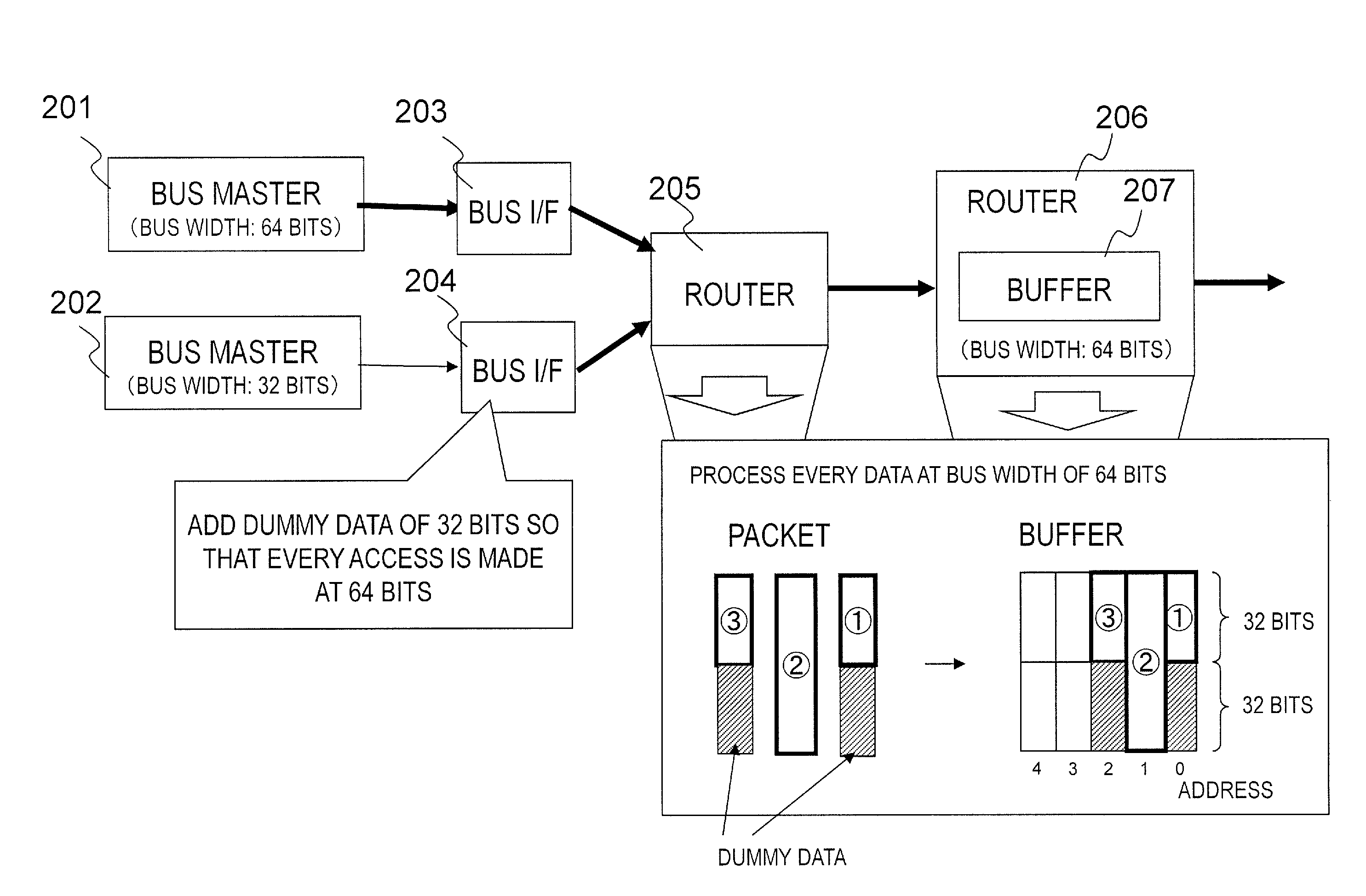
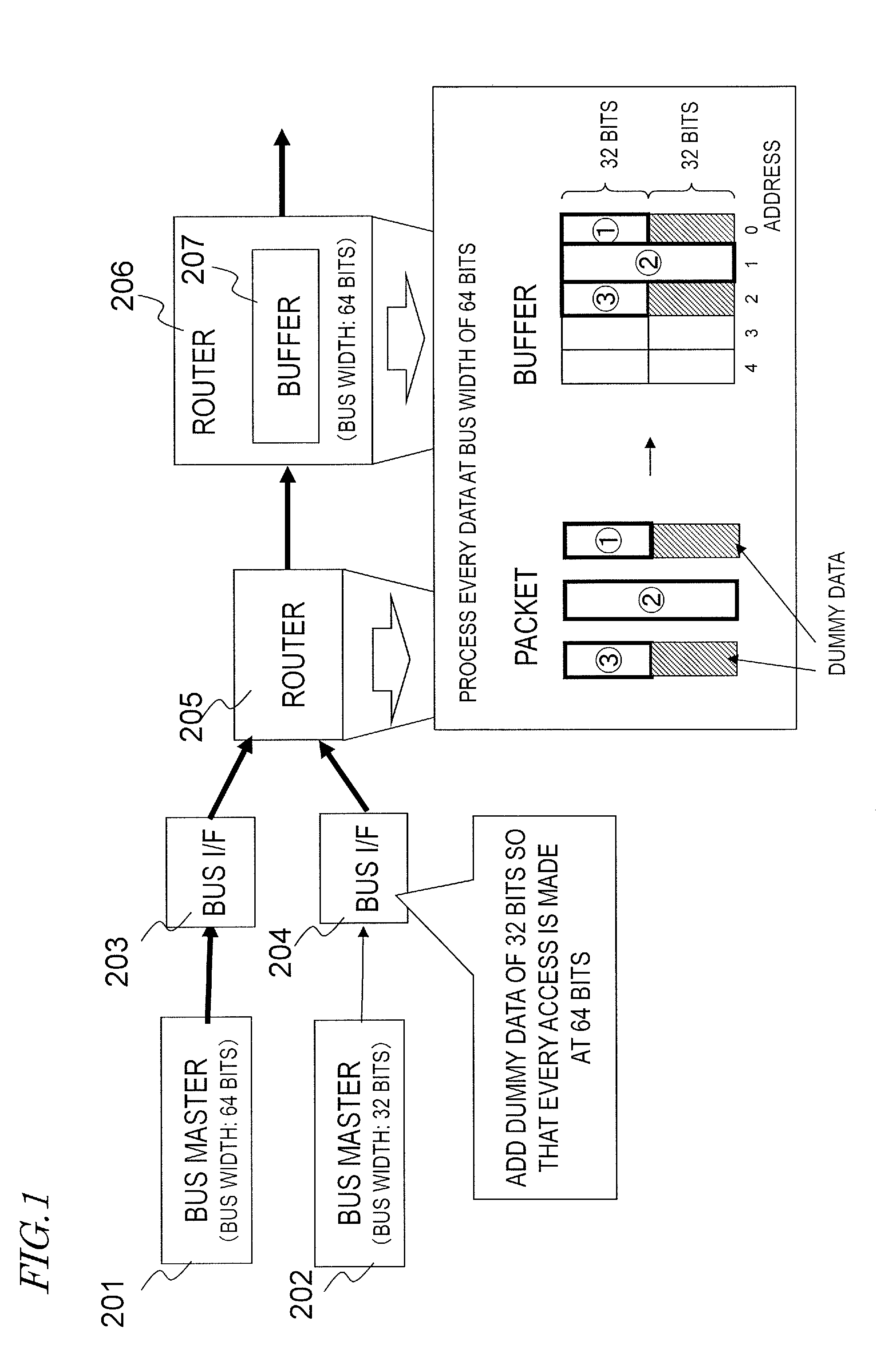
[0041]FIG. 1 illustrates how routers provided for a conventional NoC use a buffer. In the example illustrated in FIG. 1, two bus masters 201 and 202 with mutually different bus widths are connected to a router 205 via bus interface apparatuses (which will be referred to herein as “bus I / Fs”) 203 and 204, respectively. The router 205 is connected to another router 206. As will be described later with reference to FIG. 2, these routers 205 and 206 are arranged on the same system bus, which is supposed to have a unified bus width of 64 bits.

[0042]According to the present disclosure, a plurality of bus masters which use buses with mutually different widths (i.e., bus widths) for output are supposed to be present on the same NoC. In FIG. 1, the bus width used by the bus master 201 is 64 bits, while the bus width used by the bus master 202 is 32 bits. These routers 205 and 206 are supposed to manage the buffers on a 64 bit basis. This “bus width” refers herein to the number of bits of dat...


PUM


Abstract

In the bus system, bus interface apparatuses and routers are connected together through packet exchange buses which have been established on the integrated circuit. The bus interface apparatuses are respectively connected to transmission nodes which transmit data of mutually different numbers of bits in one cycle of operation of the bus system. Each of the bus interface apparatuses generates and transmits a packet based on data received from the transmission node connected and header information including size information indicating the number of bits with respect to the transmission node connected. The router analyzes the packet, gets the size information from the header information, determines how to allocate a space in the buffer for storage by reference to the size information gotten, and stores the received packet in the buffer.

Description

[0001]This is a continuation of International Application No. PCT / JP2013 / 006823, with an international filing date of Nov. 20, 2013, which claims priority of Japanese Patent Application No. 2013-011952, filed on Jan. 25, 2013, the contents of which are hereby incorporated by reference.BACKGROUND[0002]1. Technical Field[0003]The present application relates to a technique for using a buffer more efficiently in a router which transfers data to be transmitted and received between a bus master and a slave in a semiconductor integrated circuit including a networked semiconductor bus.[0004]2. Description of the Related Art[0005]In developing an integrated circuit, some people attempt to advance their development more efficiently by recycling and merging together a number of existent bus masters in order to realize the intended function and performance. To make such a development, various kinds of bus masters with mutually different bus widths, bus protocols and required qualities need to b...

Claims


Application Information

Patent Timeline
Patent Type & Authority Applications(United States)
IPC IPC(8): H04L12/863H04L12/741H04L45/74
CPCH04L45/74H04L47/62G06F13/4059Y02D10/00
Inventor YOSHIDA, ATSUSHITOKUTSU, SATORUISHII, TOMOKIYAMAGUCHI, TAKAOSOGA, YUUKI
Owner PANASONIC INTELLECTUAL PROPERTY MANAGEMENT CO LTD
Why Eureka
Try Eureka