Wireless thermometer

Active Publication Date: 2015-01-08
MURATA MFG CO LTD
View PDF0 Cites 9 Cited by
  • Summary
  • Abstract
  • Description
  • Claims
  • Application Information

AI Technical Summary

Benefits of technology

[0011]An attempt to reduce the size of the thermometer results in a reduced size of the antenna. For example, when the antenna has a winding shape, the number of the turns of the antenna is reduced. This reduces the distance the measurement resu

Problems solved by technology

This degrades the accuracy in the m

Method used


Image

  • Wireless thermometer
  • Wireless thermometer
  • Wireless thermometer

Examples


Example

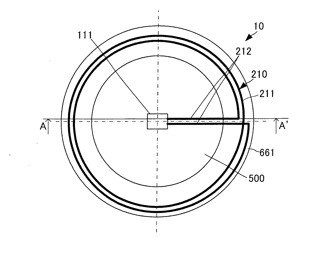
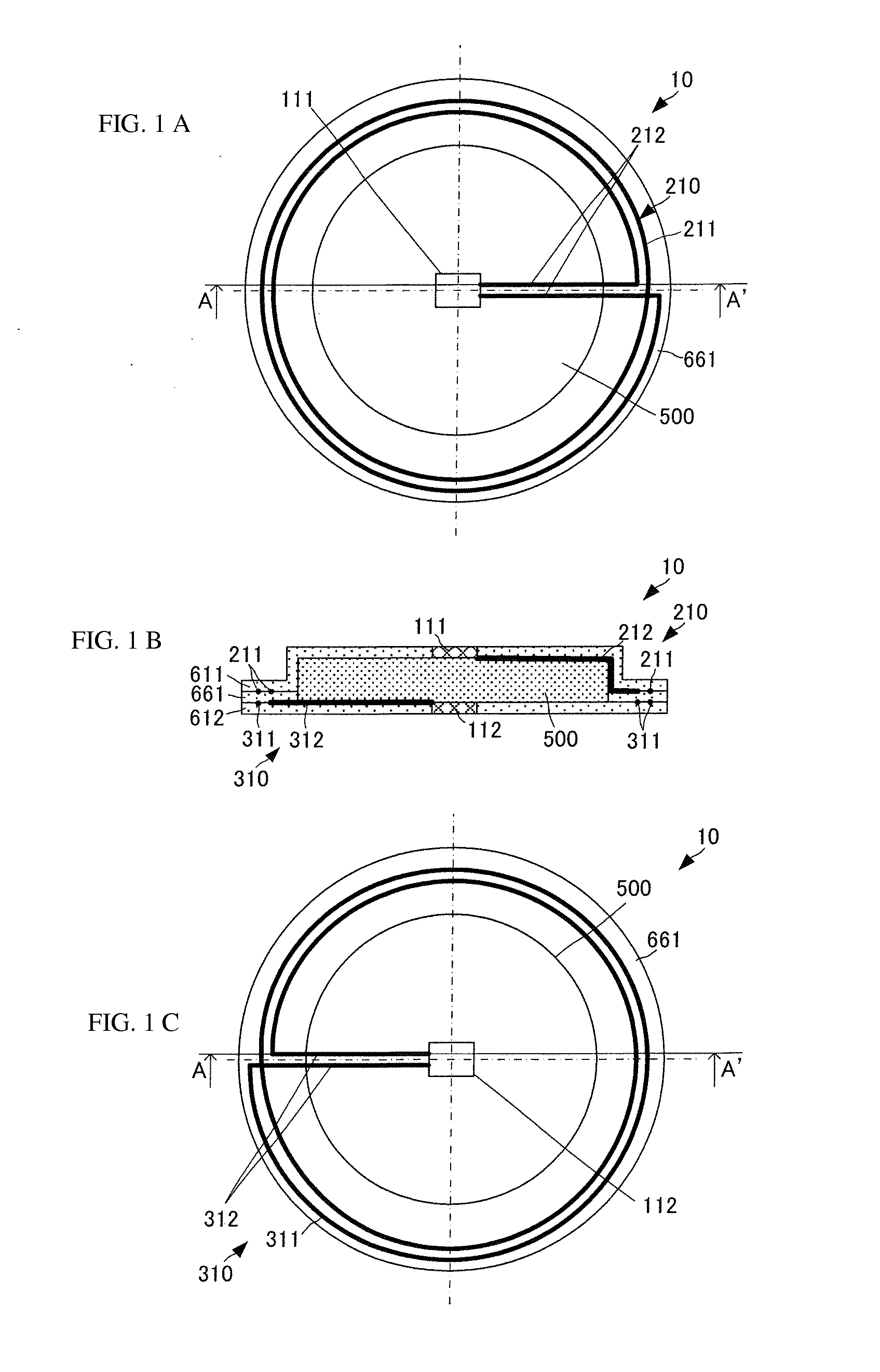
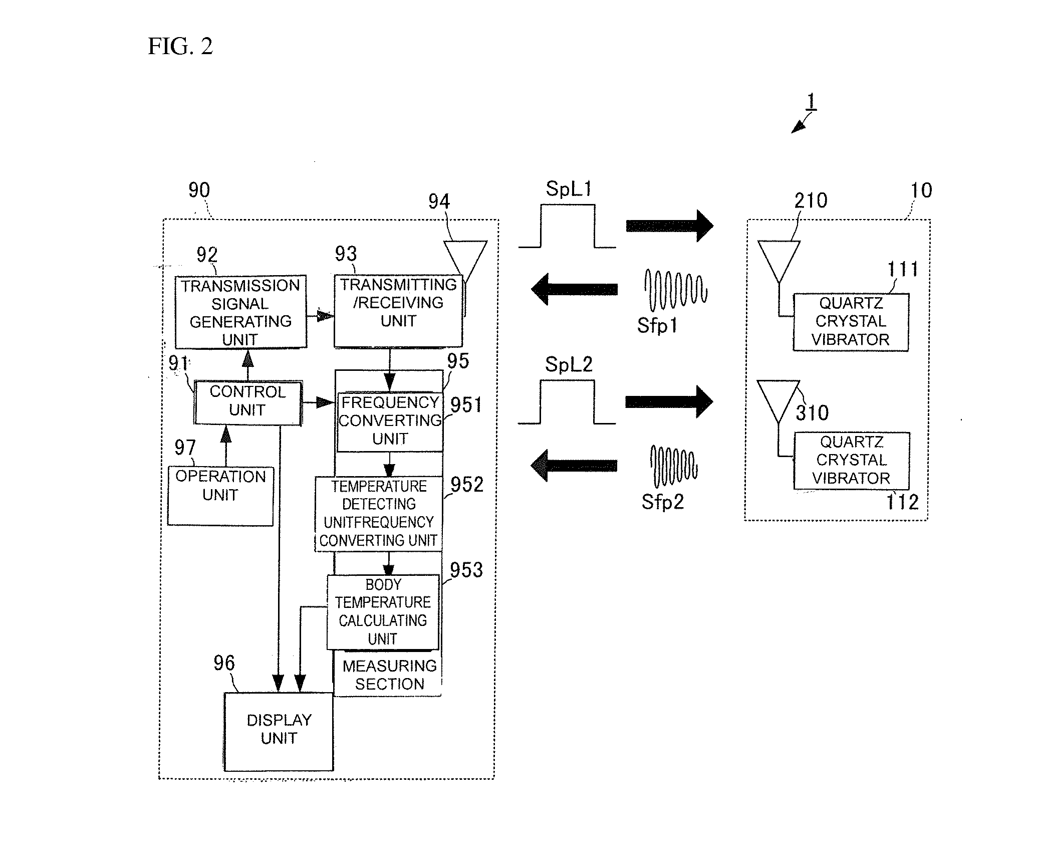
[0068]A wireless thermometer according to a first embodiment of the present invention will be described with reference to the drawings. The present embodiment deals with the case where a wireless thermometer 10 and a portable base terminal 90 communicate with each other through magnetic field coupling. The communication method is not limited to magnetic field coupling, and may be another wireless communication method. For example, the communication may be made through electric field coupling or radio waves. FIG. 1 illustrates a configuration of the wireless thermometer 10 according to the present embodiment. FIG. 1(A) is its top view with a top heat insulator 611 omitted, FIG. 1(B) is a cross-sectional view taken along line A-A′ of FIGS. 1(A) and 1(C), and FIG. 1(C) is its bottom view with a bottom heat insulator 612 omitted.

[0069]The wireless thermometer 10 includes a heat insulator 500 having flexibility, insulating properties, and a predetermined thermal resistivity ρT. The heat ...

Example

[0104]A wireless thermometer according to a second embodiment of the present invention will now be described with reference to the drawings. FIG. 3 illustrates a configuration of a wireless thermometer 10A according to the second embodiment of the present invention. FIG. 3(A) is a top view with a top heat insulator 611A omitted, FIG. 3(B) is a cross-sectional view taken along line A-A′ of FIGS. 3(A) and 3(C), and FIG. 3(C) is a bottom view with a bottom heat insulator 612A omitted.

[0105]The wireless thermometer 10A of the present embodiment differs from the wireless thermometer 10 of the first embodiment in the shape of an antenna 310A, but the other configuration of the wireless thermometer 10A is the same as that of the wireless thermometer 10.

[0106]In plan view of the wireless thermometer 10A, a winding conductor 311A of the antenna 310A is overlapped with the winding conductor 211 of the antenna 210 over substantially the entire length thereof. Also in plan view of the wireless ...

Example

[0108]A wireless thermometer according to a third embodiment will now be described with reference to the drawings. FIG. 4 illustrates a configuration of a wireless thermometer 10B according to the third embodiment of the present invention. FIG. 4(A) is a top view with a top heat insulator 611B omitted, FIG. 4(B) is a cross-sectional view taken along line A-A′ of FIGS. 4(A) and 4(C), and FIG. 4(C) is a bottom view with a bottom heat insulator 612B omitted.

[0109]The wireless thermometer 10B of the present embodiment includes two quartz crystal vibrators corresponding to the first temperature detecting means of the present invention, and two quartz crystal vibrators corresponding to the second temperature detecting means of the present invention. The number of quartz crystal vibrators is not limited to this, and there may be three or more quartz crystal vibrators each, or the number of quartz crystal vibrators serving as the first temperature detecting means may differ from the number ...


PUM


Abstract

A wireless thermometer is provided, which measures a deep temperature with high accuracy and has an improved communication distance. A wireless thermometer includes a flat film-like substrate. A quartz crystal vibrator and an antenna are disposed on a principal surface of the substrate. A quartz crystal vibrator and an antenna are disposed on the other principal surface of the substrate. A winding conductor of the antenna is substantially symmetrical with a winding conductor of the antenna with respect to the substrate. A lead conductor of the antenna is connected to the winding conductor at one end and is connected to the quartz crystal vibrator at the other end. A central portion of the lead conductor is bent. By folding the central portion, the quartz crystal vibrator can be positioned opposite the quartz crystal vibrator with a heat insulator interposed there between.

Description

BACKGROUND OF THE INVENTION[0001]1. Field of the Invention[0002]The present invention relates to a wireless thermometer that measures a physical quantity determined by a temperature of an object whose temperature is to be measured, and wirelessly transmits the physical quantity to an external device.[0003]2. Description of the Related Art[0004]Conventionally, various deep temperature measuring devices have been devised, which measure not only a surface temperature of an object but also a deep temperature of the object. For example, a deep temperature measuring device is disclosed in Patent Document 1. The deep temperature measuring device disclosed in Patent Document 1 includes a first temperature sensor (surface-side temperature sensor) group mounted on a surface of an object whose temperature is to be measured (hereinafter simply referred to as an object) and a second temperature sensor temperature (outside-air-side temperature sensor) group disposed at a position spaced by a pred...

Claims


Application Information

Patent Timeline
IPC IPC(8): G01K1/02G01K13/00
CPCG01K13/00G01K1/024G01K7/32G01K13/20
Inventor ITO, YOSHIHIROHOSHINO, YURI
Owner MURATA MFG CO LTD
Why Eureka
Try Eureka