

Waveguide slotted array antenna
- Summary
- Abstract
- Description
- Claims
- Application Information
AI Technical Summary
Benefits of technology
Problems solved by technology
Method used
Image

Examples
first embodiment
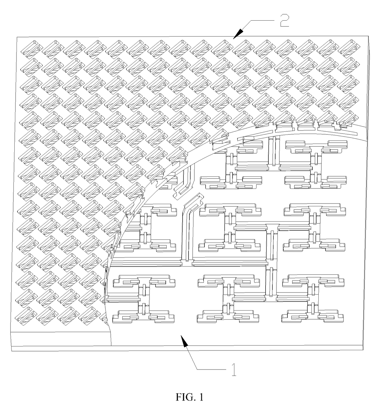
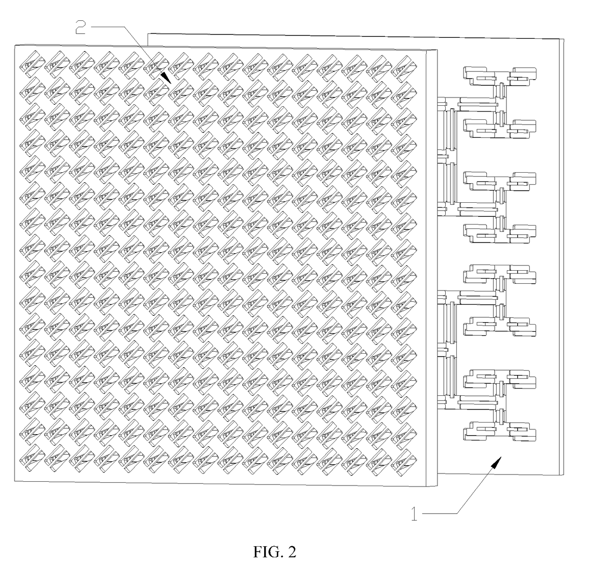
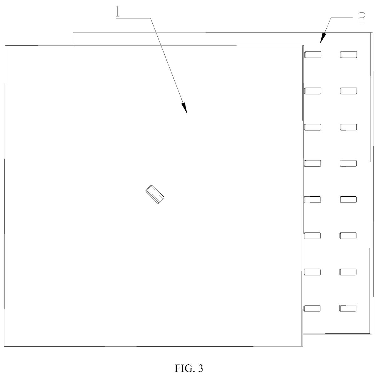
[0030] as is shown in FIGS. 1-9, a waveguide slotted array antenna comprises a feed layer 1 and a radiation layer 2, wherein the feed layer 1 is located below the radiation layer 2, and the radiation layer 2 comprises a first radiation unit, a second radiation unit, a third radiation unit and a fourth radiation unit which are stacked from bottom to top.
[0031]The first radiation unit comprises a first flat metal plate 3 and a first radiation array arranged on the first flat metal plate 3; the first radiation array comprises n2 radiation cavities 4 which are arranged at intervals, wherein n=2k, and k is a positive integer which is equal to or greater than two; the radiation cavities 4 are rectangular concave cavities formed in the upper surface of the first flat metal plate 3, and the n2 radiation cavities 4 are distributed on the first flat metal plate 3 in n columns and n rows; first matching plates 5 are separately arranged in the middle of the front side wall and the middle of the...
second embodiment
[0040] as is shown in FIGS. 1-9, a waveguide slotted array antenna comprises a feed layer 1 and a radiation layer 2, wherein the feed layer 1 is located below the radiation layer 2, and the radiation layer 2 comprises a first radiation unit, a second radiation unit, a third radiation unit and a fourth radiation unit which are stacked from bottom to top.
[0041]The first radiation unit comprises a first flat metal plate 3 and a first radiation array arranged on the first flat metal plate 3; the first radiation array comprises n2 radiation cavities 4 which are arranged at intervals, wherein n=2k, and k is a positive integer which is equal to or greater than two; the radiation cavities 4 are rectangular concave cavities formed in the upper surface of the first flat metal plate 3, and the n2 radiation cavities 4 are distributed on the first flat metal plate 3 in n columns and n rows; first matching plates 5 are separately arranged in the middle of the front side wall and the middle of the...
PUM
 Abstract
Description
Claims
Application Information