Antenna with partially saturated dispersive ferromagnetic substrate

Active Publication Date: 2020-07-23
TDF CORP +1
View PDF0 Cites 0 Cited by
  • Summary
  • Abstract
  • Description
  • Claims
  • Application Information

AI Technical Summary

Benefits of technology

The patent describes an antenna design that uses a dispersive ferritic substrate for improved radiation effectiveness and a reduced size. By modifying the magnetic features of the substrate, the relative magnetic permeability and magnetic losses are reduced. This gradual and local modification compensates for the radiation reduction and stabilizes the impedance, resulting in a suitable gain with reduced heating. Compared to other antennas, the size of the ferrites is larger, leading to improved effectiveness and increased directivity. Stacked antennas can achieve greater gains, and the degree of saturation of the dispersive ferrites can be modified according to the layers for better adaptation and performance.

Problems solved by technology

By definition, a dispersive ferrite presents high dielectric losses and / or high magnetic losses.
In addition, the dispersive ferrite can see a rapid heating and a degradation of performances in the vicinity of the Curie point during long-duration and high-power emissions.

Method used


Image

  • Antenna with partially saturated dispersive ferromagnetic substrate
  • Antenna with partially saturated dispersive ferromagnetic substrate
  • Antenna with partially saturated dispersive ferromagnetic substrate

Examples


third embodiment

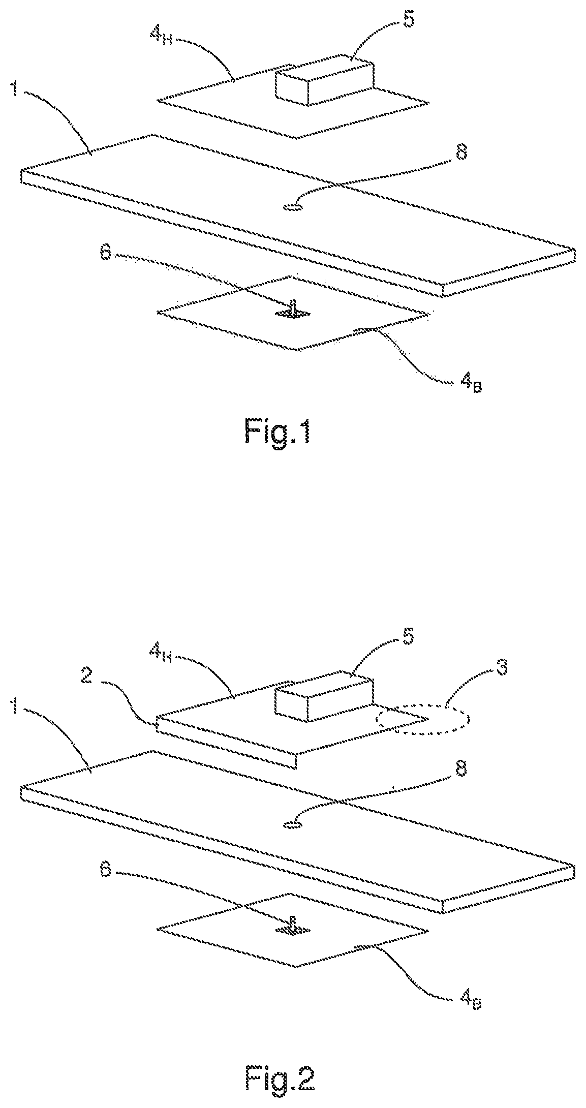
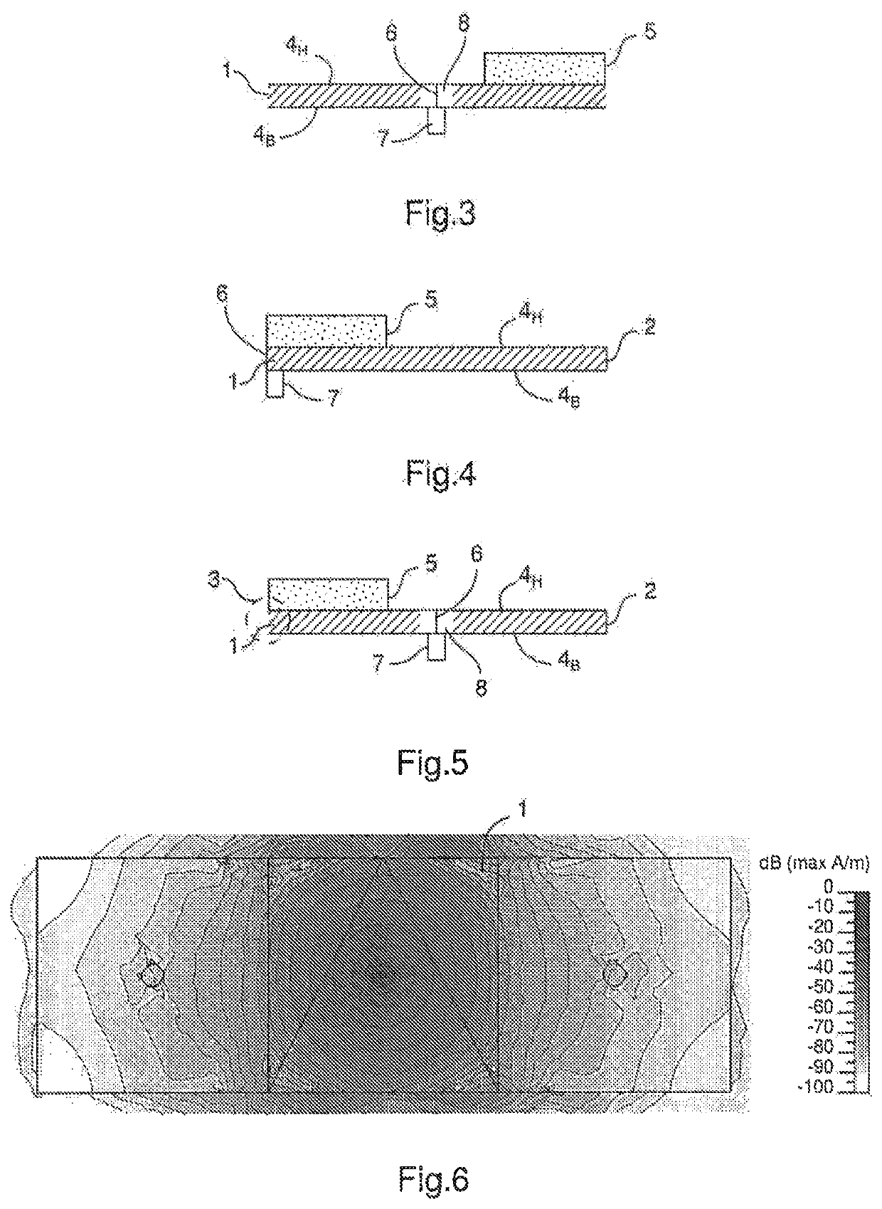
[0079]FIG. 4 schematically, laterally cross-sectionally represents an antenna according to the invention.

[0080]This embodiment is similar to the second embodiment wherein the excitor 6 is no longer arranged at the centre of the ferrite and passing through it, but on an edge of the ferrite so as to extend between the mass plane 4B and the radiating portion 4H, at the level of the opening of the second embodiment. The excitor 6, the radiating portion 4H, the short-circuit 2 and the mass plane 4B thus form a loop, the antenna also being an antenna of the loop type.

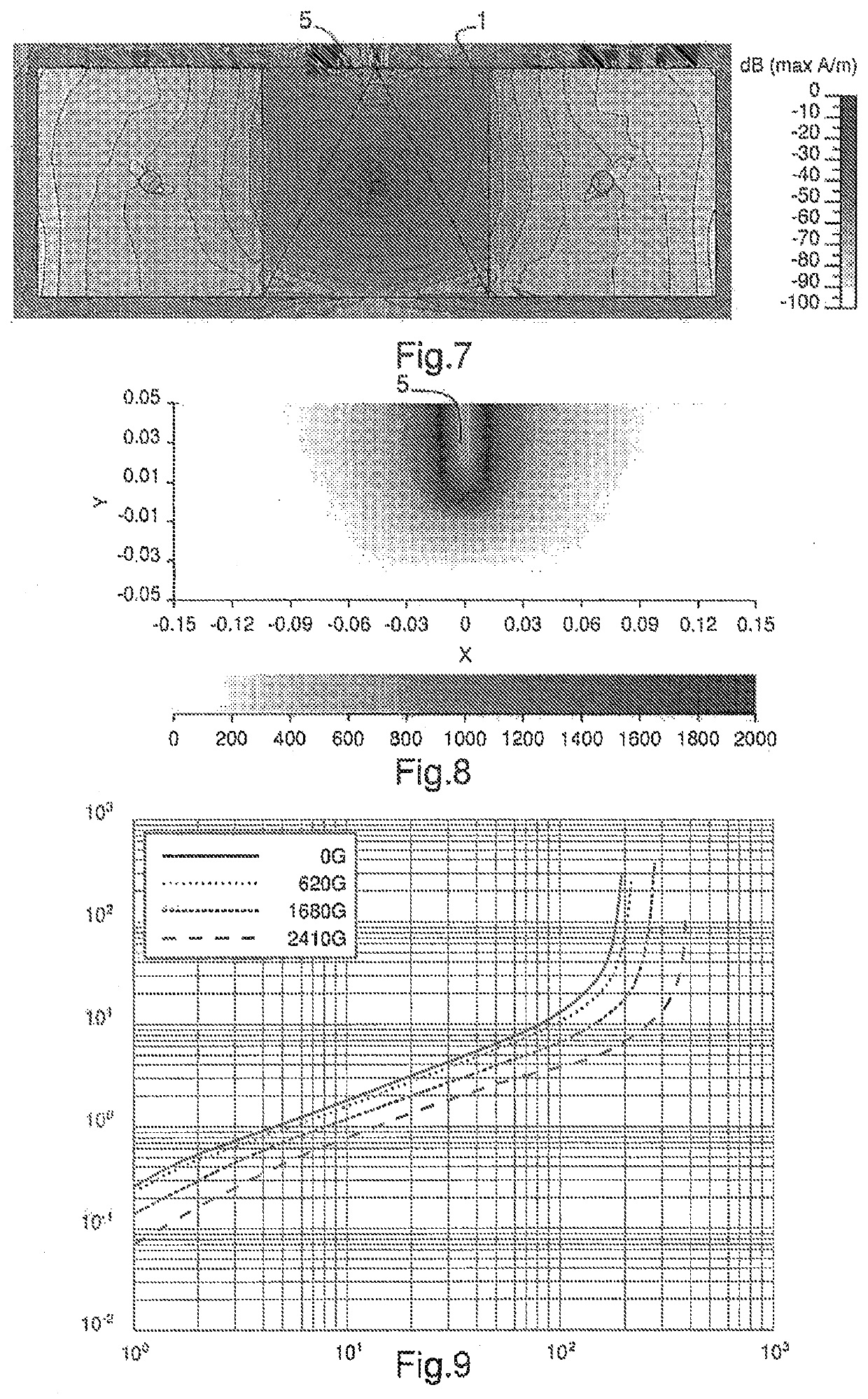
[0081]FIG. 6 is a magnetic field mapping representing the distribution of the radiofrequency magnetic field in the dispersive ferrite of an antenna as a top view according to the first embodiment of the invention with no magnet, and FIG. 7 is a magnetic field mapping representing the distribution of the radiofrequency magnetic field in the dispersive ferrite of an antenna as a top view according to the first embodiment of the...

first embodiment

[0097]FIG. 14 is a graph representing the reflection coefficient S11 of an antenna according to the invention in the absence (SA curve—“no magnet”) or in the presence (AA curve—“with magnet”) of a permanent magnet of 2000 G, according to the frequency (in MHz). The antenna is here of the monopole type.

second embodiment

[0098]FIG. 15 is a graph representing the reflection coefficient S11 of an antenna according to the invention in the absence (SA curve) or in the presence (AA curve) of a permanent magnet of 2000 G, according to the frequency (in MHz). The antenna is here of the semi-open type.

[0099]FIG. 16 is a diagram of radiation of an antenna according to the first embodiment of the invention in the absence (SA curve) or in the presence (AA curve) of a permanent magnet of 2000 G.

[0100]The antenna with no magnet is an omnidirectional antenna of low gain, while the antenna of the monopole type with a magnet according to the invention is directional and has a greater gain in all directions. FIG. 17 is a diagram of radiation of an antenna according to the second embodiment of the invention in the absence (SA curve) or in the presence (AA curve) of a permanent magnet of 2000 G.

[0101]The antenna with no magnet is a directional antenna of low gain, while the semi-open antenna with a magnet according to...


PUM


Abstract

The invention concerns an antenna, comprising at least two non-ferrous metal plates, at least one first plate forming a radiating portion and a second plate forming a mass plane, at least one substrate, arranged between the mass plane and the radiating portion, and an excitor of length at least equal to the thickness of the substrate, extending between the mass plane and the radiating portion and connected to the radiating portion, and adapted to supply the antenna, characterised in that the substrate is a dispersive ferromagnetic substrate, called dispersive ferrite presenting, as magnetic features, a high relative magnetic permeability comprised between 10 and 10,000 and a high magnetic loss tangent greater than 0.1, said antenna comprising means for gradually and locally reducing magnetic features of the dispersive ferrite.

Description

1. TECHNICAL FIELD OF THE INVENTION[0001]The invention concerns an antenna on a ferromagnetic substrate. In particular, the invention concerns an antenna on an ultracompact ferromagnetic substrate in the vertical plane compared with the wavelength, which could be used in reception or in emission in the kilometric (30-300 kHz), hectometric (0.3-3 MHz), decametric (3-30 MHz) and metric (30-300 MHz) frequency bands.[0002]The antenna is particularly suitable, for example, in broadband or narrowband emission systems with a medium to high-power conveying information in the form of signals modulated or not and which are spread by radio. According to certain embodiments, the antenna favours the propagation of the wave in a favoured direction (directive antenna).2. TECHNOLOGICAL BACKGROUND[0003]Electrically small antennas have an impedance presenting a strong reactive component which does not allow their use in an effective and direct manner in standardised real impedance systems (typically ...

Claims


Application Information

Patent Timeline
IPC IPC(8): H01Q3/44H01Q1/38
CPCH01Q3/44H01Q1/38H01Q1/00H01Q7/08H01Q7/005
Inventor KAVERINE, EVGUENIPALUD, SÉBASTIENCOLOMBEL, FRANCKHIMDI, MOHAMED
Owner TDF CORP
Why Eureka
Try Eureka