Supercharge Your Innovation With Domain-Expert AI Agents!

Power control system and method thereof

Active Publication Date: 2015-01-08
GIGA BYTE TECH CO LTD
View PDF5 Cites 2 Cited by
  • Summary
  • Abstract
  • Description
  • Claims
  • Application Information

AI Technical Summary

Benefits of technology

The power control system described in this patent allows the computer and power system to work separately, which can prevent frequent powering off and on of the power system that may occur when the computer is overclocked. This results in extending the lifetime of the computer device and maintaining its performance, while also preventing malfunctions in the computer device's hardware.

Problems solved by technology

However, when the CPU is operated with overclocking frequency, the computer device 100 often spontaneously enters the power-off state and then resumes powering on again.
This frequent on-and-off operation shortens the service lifetime of the components of the computer device.
In addition, the on-and-off operations in some components such as the operation of motors or fans also cause extra noise.
More importantly, when the CPU is operated with overclocking frequency, the CPU often generates huge heat.

Method used


Image

  • Power control system and method thereof
  • Power control system and method thereof
  • Power control system and method thereof

Examples


first embodiment

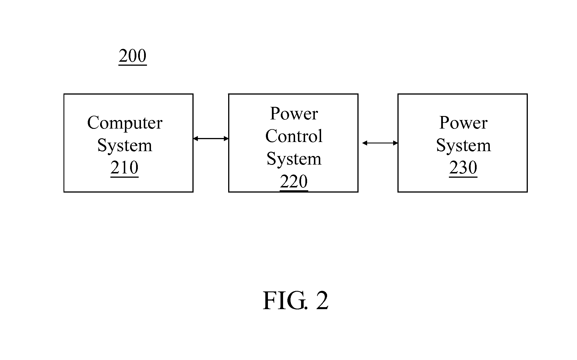
[0038]Please firstly refer to FIG. 2, where FIG. 2 is a block diagram showing a power control system and the computer device to which the power control system is applied in accordance with the present invention. The computer device 200 includes a computer system 210 and a power system 230. The computer system 210 includes essential hardware components required for the operation functions of the operating system (OS) in the computer device 200. Hence, the computer system 210 includes at least one CPU or further includes a southbridge chipset, a northbridge chipset, or other hardware components. It is notable that with the improvement of the technique in semiconductor field, the integrated circuit (IC) has become highly integrated. Therefore, the cross-line to distinguish the function blocks by each unit of the integrated circuit becomes vague. For example, the northbridge chipset, used to be an independent component in computer devices, has been integrated into the CPU to form a sing...

fifth embodiment

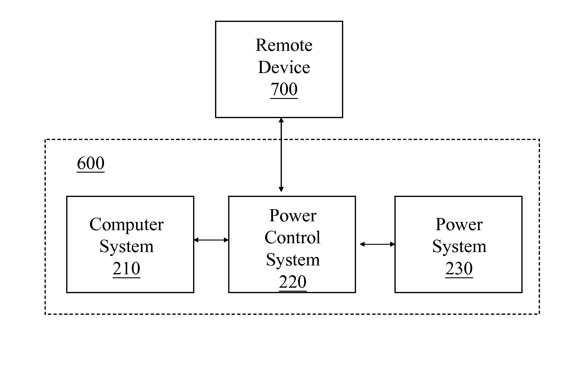
[0047]Please refer to FIG. 6, FIG. 6 is a block diagram showing a power control system and the computer device to which the power control system is applied in accordance with the present invention. The difference between the computer device 600 and the computer device 400 and the difference between the computer device 600 and the computer device 500 are that the power control system 220 of the computer device 600 is set by a remote device 700 outside the computer device 600 to execute overclocking frequency mode. The remote device 700 can be a server, a personal computer device or a portable electronic device. The remote device 700 can be connected to, but should not be limited to, the computer device 600 via a physical Ethernet or Wi-Fi. The characteristics and functions of the computer system 210, the power control system 220, and the power system 230 of the computer device 600 are similar as those of the computer device 200; please refer to the FIG. 2 and the related description ...


PUM


Abstract

A power control system and a power control method thereof applied to a computer device are provided. The computer device includes a computer system and a power system. The power system includes a plurality of voltage regulators for providing supply voltages to the components of the computer device. The power control system is coupled to the computer system and the power system and includes an overclocking frequency mode. When the computer system receives an OFF signal and enters a non-operating mode, and when the power control system is in the overclocking frequency mode, the power control system sends a SYSTEM-SHUTDOWN signal to the computer system to control the power system to enter the non-operating mode and to control the power system to keep outputting supply voltages.

Description

CROSS-REFERENCE TO RELATED APPLICATIONS[0001]This application claims the benefit of the filing date of Taiwan Patent Application No 102124273, filed on Jul. 5, 2013, in the Taiwan Intellectual Property Office, the disclosure of which is incorporated herein in its entirety by reference.BACKGROUND OF THE INVENTION[0002]1. Field of the Invention[0003]This disclosure relates to a power control system and a power control method and, more particularly, to a power control system and a power control method which allow the computer system and the power system of a computer device separately stay in different operating modes.[0004]2. Description of the Related Art[0005]In a common computer device, a central processing unit (CPU) is regarded as the brain of a computer device for processing the core tasks of the computer device. In particular, a clock frequency that the CPU is operating on is an important performance indicator. The higher the clock frequency is, the faster the computer device c...

Claims


Application Information

Patent Timeline
IPC IPC(8): G06F1/32
CPCG06F1/3203G06F1/20G06F1/26G06F1/3206
Inventor LIAO, TSE HSINEHUANG, CHIH WEIKE, CHIH HUACHEN, HUNG CHENG
Owner GIGA BYTE TECH CO LTD
Features
  • R&D
  • Intellectual Property
  • Life Sciences
  • Materials
  • Tech Scout
  • Unparalleled Data Quality
  • Higher Quality Content
  • 60% Fewer Hallucinations
Learn More