Eureka AIR delivers breakthrough ideas for toughest innovation challenges, trusted by R&D personnel around the world.

Valve positioner having bypass component and control valve comprised thereof

a valve positioner and bypass technology, applied in the direction of fluidic programme control, valve operating means/release devices, transportation and packaging, etc., can solve the problems of valve downtime for repair and/or replacement of defective components, valve failure, and process system inoperable for extended periods of time, so as to reduce downtime

Active Publication Date: 2015-01-15
DRESSER LLC
View PDF17 Cites 5 Cited by
  • Summary
  • Abstract
  • Description
  • Claims
  • Application Information

AI Technical Summary

Benefits of technology

The patent describes improvements to valve positioners that allow control valves to continue operating even if digital components fail. These improvements include a by-pass component that can maintain operation using control input signals without needing the digital microprocessor. The technical effect of this is that it reduces downtime for repairs and the valve positioner can continue to control fluid flow with minimal disruption.

Problems solved by technology

Unfortunately, although digital-based valve positioners are more powerful and accurate than conventional mechanical and / or early digital devices, these types of valve positioners still have reliability issues and can fail.
Failures often lead to valve downtime for repair and / or replacement of the defective components.
More important, however, is that failures that require maintenance of the control valve can render the process system inoperable for extended periods of time.
The resulting downtime can lead to expensive production delays and, possibly, run afoul of regulations set forth by any number of government organizations (e.g., the Environmental Protection Agency (EPA), the Occupational Safety and Health Administration (OSHA), etc.).
Most solutions that address the reliability of digital components provide little relief to shorten, or to avoid, downtime of control valves that utilize digital-based valve positioners.
However, solenoids provide only binary operation (e.g., on / off), which does not allow finite modulation of flow through the control valve.
Although effective to remedy potential downtime, these redundant systems still require additional hardware and software that can add significant component cost and complexity to the process line and control system.

Method used


Image

  • Valve positioner having bypass component and control valve comprised thereof
  • Valve positioner having bypass component and control valve comprised thereof
  • Valve positioner having bypass component and control valve comprised thereof

Examples


Embodiment Construction

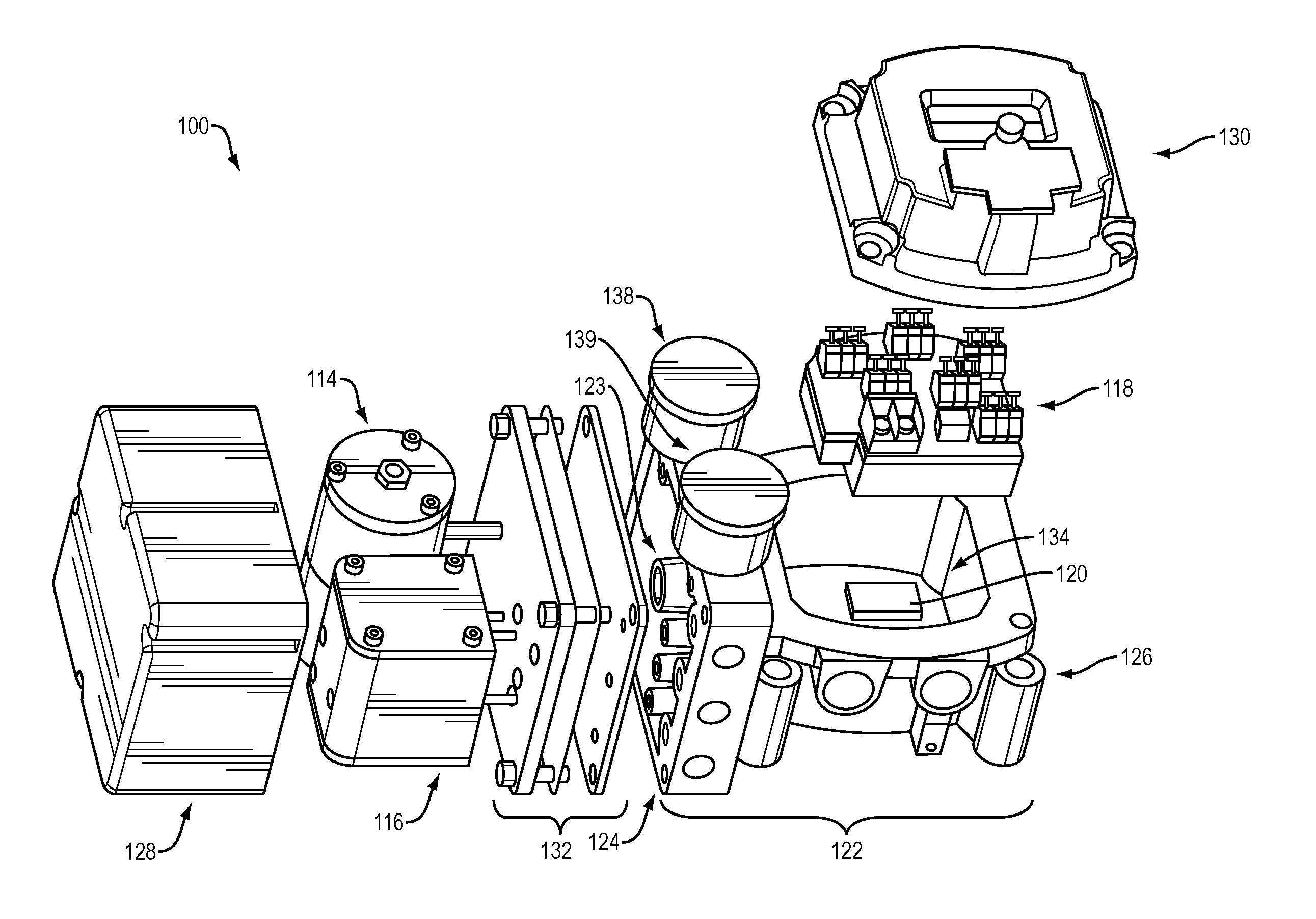
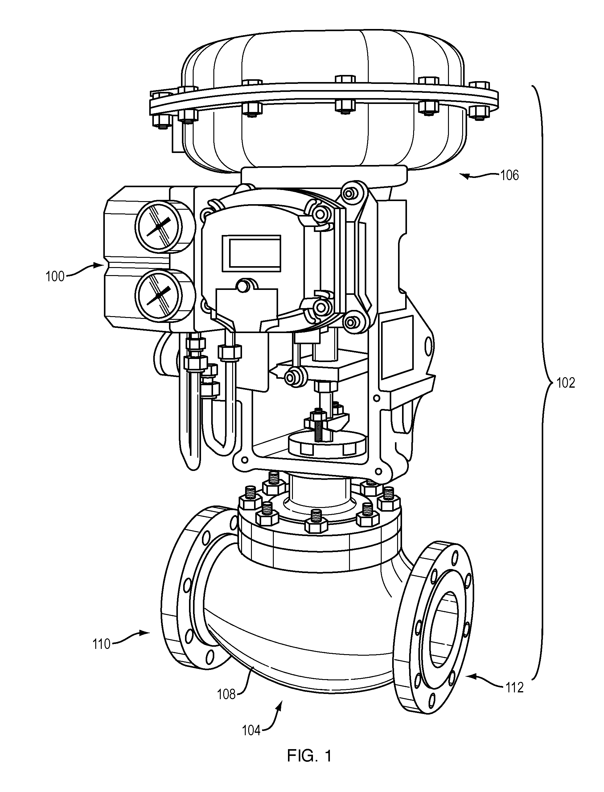
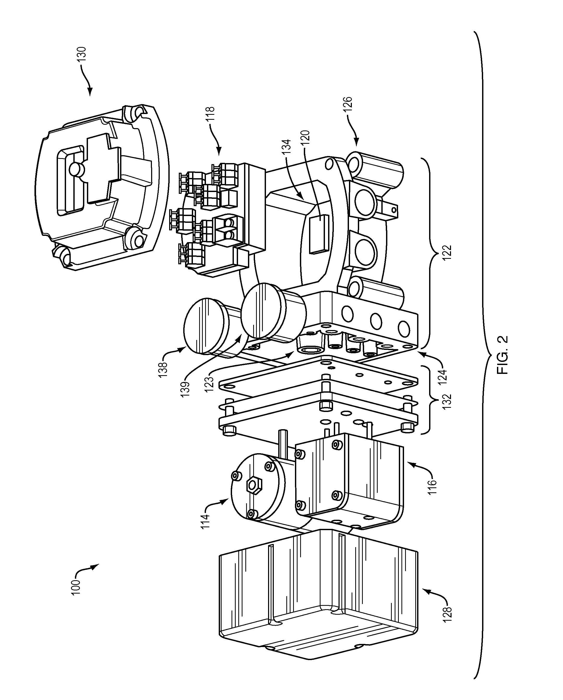
[0016]FIGS. 1 and 2 illustrate an exemplary embodiment of a valve positioner 100 with by-pass features that continue to modulate fluid flow during on-line maintenance and repair. In FIG. 1, the valve positioner 100 is part of a control valve 102 with a fluid coupling 104 and an actuator 106. These components of the control valve 102 work in combination with the valve positioner 100 to control one or more process conditions (e.g., flow, pressure, temperature, etc.) that relate to fluid flow through the fluid coupling 104. As shown in the diagram, the fluid coupling 104 has a body 108 with a first inlet / outlet 110 and a second inlet / outlet 112. The fluid coupling 104 can also have a valve, which is not shown in the diagram of FIG. 1. The valve resides in the body 108. The actuator 106 couples with the valve to change the position of the valve (e.g., from a first valve position to a second valve position). The change in position modulates fluid flow across the first inlet / outlet 110 an...


PUM


Abstract

Embodiments of a valve positioner that can maintain operation of the control valve despite failures in one or more components. These embodiments reduce downtime by allowing in-situ repair to occur on the valve positioner. In one embodiment, the valve positioner incorporates a by-pass component, which can utilize control input signals (e.g., a 4-20 mA signal) to energize one or more components (e.g., a current-to-pressure converter) to cause the control valve to modulate fluid flow without the digital microprocessor and / or related components.

Description

BACKGROUND[0001]The subject matter disclosed herein relates to control valves and, in particular, to embodiments of a valve positioner for control valves.[0002]Control valves regulate transmission and distribution of fluids (e.g., liquids and gases). These devices integrate into process control systems in a wide variety of industries. Examples of process control systems form a control loop with remote sensors and other feedback elements to monitor process conditions (e.g., temperature, pressure, etc.). The control loop can generate signals that cause the control valve to modify the flow of fluid in response to changes in the process conditions.[0003]Many control valves integrate valve positioners with digital components (e.g., microprocessors) that can process these signals. These digital components afford the control valve with precise control and functionality. Certain types of digital components can also expand data processing and communication capabilities of the valve positione...

Claims


Application Information

Patent Timeline
IPC IPC(8): F15B15/20
CPCF15B15/202F15B5/006F16K37/0091G05B19/43Y10T137/7761F15B21/08
Inventor ESPOSITO, SANDRO
Owner DRESSER LLC
Why Eureka
Eureka Blog
Learn More