Induction Welding System

a welding system and welding technology, applied in the field of induction welding, can solve the problems of repeated distortion of the magnetic domain of the ferromagnetic workpiece, heat the workpiece, and heat generation

Active Publication Date: 2015-01-15
THE BOEING CO
View PDF6 Cites 9 Cited by
  • Summary
  • Abstract
  • Description
  • Claims
  • Application Information

AI Technical Summary

Benefits of technology

[0010]In another illustrative embodiment, an induction welding system comprises an induction heating system, a retaining structure, and a number of weld stack-ups. The retaining structure is configured to retain a first workpiece and a second workpiece configured to be induction-welded to the first workpiece at a number of weld locations. Each weld stack-up in the number of weld stack-up is configured to be positioned at a corresponding weld location in the number of weld locations to prevent an undesired current path from forming at the corresponding weld location during induction heating of the first workpiece and the second workpiece by the induction heating system.

Problems solved by technology

This electromagnetic field may heat the workpiece.
When the workpiece is a ferromagnetic workpiece, the heating may be caused by hysteresis.
In particular, the electromagnetic field may cause repeated distortions of the magnetic domains of the ferromagnetic workpiece.
However, in some situations, when using susceptor wires and large induction coils in the form of solenoids to perform induction welding, undesirable current paths may be formed.
These current paths may cause portions of a workpiece that were not intended to be heated to become hot.
In some cases, these current paths may cause portions of a workpiece to become overheated.
This overheating may cause undesired inconsistencies to develop in and / or on the workpiece.
For example, a portion of a workpiece that is overheated may burn.

Method used


Image

  • Induction Welding System
  • Induction Welding System
  • Induction Welding System

Examples


Embodiment Construction

[0026]The illustrative embodiments recognize and take into account different considerations. For example, the illustrative embodiments recognize and take into account that it may be desirable to have a method and apparatus for interrupting undesired current paths that may form during induction welding and / or preventing the formation of these undesired current paths. The illustrative embodiments recognize and take into account that one or more fiberglass layers may be capable of interrupting these types of current paths. Thus, the illustrative embodiments provide a method and apparatus for performing induction welding.

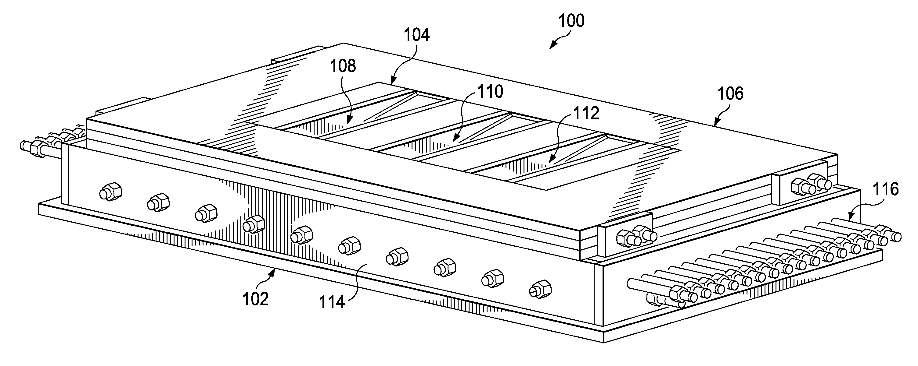
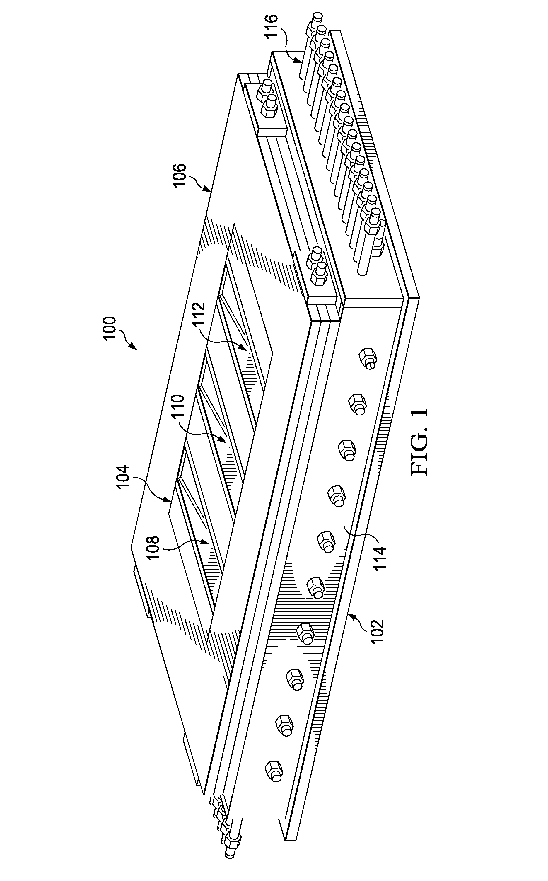
[0027]Referring now to the figures and, in particular, with reference to FIG. 1, an illustration of a partially assembled induction welding system is depicted in accordance with an illustrative embodiment. In this illustrative example, induction welding system 100 may include first base 102 and retaining structure 104.

[0028]As depicted, retaining structure 104 may hold ...


PUM

PropertyMeasurementUnit
frequencyaaaaaaaaaa
thermoplasticaaaaaaaaaa
electric currentaaaaaaaaaa

Abstract

A method and apparatus for performing induction welding. A number of protective layers are positioned between a susceptor layer and at least one of a plurality of workpieces at a weld location. An undesired current path is prevented from forming at the weld location during induction heating of the plurality of workpieces by the number of protective layers.

Description

BACKGROUND INFORMATION[0001]1. Field[0002]The present disclosure relates generally to induction welding and, in particular, to using induction welding to attach a skin to a number of stiffeners. Still more particularly, the present disclosure relates to a method and apparatus for attaching a skin to a number of stiffeners using at least one stack-up comprised of a susceptor layer and one or more protective layers.[0003]2. Background[0004]Induction welding is a type of welding that uses electromagnetic radiation to heat a workpiece. Typically, an induction welding system includes one or more induction coils that are energized with a radio frequency electric current, which in turn, generates a high-frequency electromagnetic field. This electromagnetic field may heat the workpiece.[0005]When the workpiece is electrically conductive, the heating may take the form of resistive heating that occurs due to induced currents, referred to as eddy currents. When the workpiece is a ferromagnetic...

Claims


Application Information

Patent Timeline
Patent Type & Authority Applications(United States)
IPC IPC(8): H05B6/10
CPCH05B6/105B29L2031/3076B29C65/368B29C65/4815B29C65/5021B29C65/5057B29C66/112B29C66/131B29C66/474B29C66/49B29C66/712B29C66/721B29C66/73921B29C66/91651B29C65/3632B29C66/91411B29C66/959B64C1/12B64C3/26B29C65/5014B29C66/003B29C66/7212B29C66/8432B29C66/8122B64F5/10B29C65/3668B29C66/532B29K2309/08B29K2909/02
Inventor MATSEN, MARC ROLLOMILLER, ROBERT JAMESDYKSTRA, WILLIAM C.
Owner THE BOEING CO
Why Eureka
Try Eureka