Functional Support with Button Functions

a multi-functional, button technology, applied in the direction of molds, household objects, applications, etc., can solve the problems of difficult to achieve the functional actuation of such a button, the film also has a strong tendency to fail quickly in the endurance test of actuation, and the gap and material transitions. achieve the effect of high-quality appearan

Inactive Publication Date: 2015-01-15
ABATEK INT
View PDF0 Cites 18 Cited by
  • Summary
  • Abstract
  • Description
  • Claims
  • Application Information

AI Technical Summary

Benefits of technology

[0015]iii) on the second side, facing away from the first side, the plastic film is flooded in the same injection mould or, after transferring the blank into a further injection mould, in this further injection mould, substantially all over with a transparent curing (self-curing, curing in the presence of a separate curing agent, and / or thermosetting) casting compound in an RIM process (reaction injection moulding), and is coated to form a continuous transparent surface layer with a thickness of at least 0.1 mm over substantially the entire functional support, membrane regions that are flexible at least in places being formed in the region of the clearances (in this respect it is also possible for the mould to be closed somewhat further after injection of the casting compound, so that a very thin layer of casting compound is possible);
[0026]It may in this respect be advantageous if, when closing and / or opening the mould, the plastic film is automatically cut right away to a peripheral contour.

Problems solved by technology

This results in gaps and material transitions.
The functional actuation of such a button is also not simple to achieve, since the deformed film also has to follow the travel of the button when it is depressed.
Such films also have a strong tendency to fail quickly in an actuation endurance test.

Method used


Image

  • Functional Support with Button Functions
  • Functional Support with Button Functions
  • Functional Support with Button Functions

Examples


Embodiment Construction

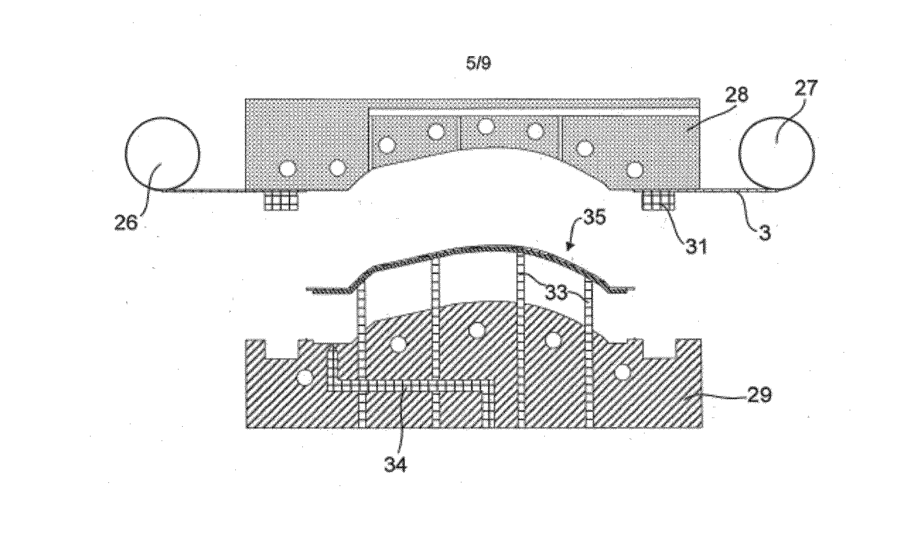
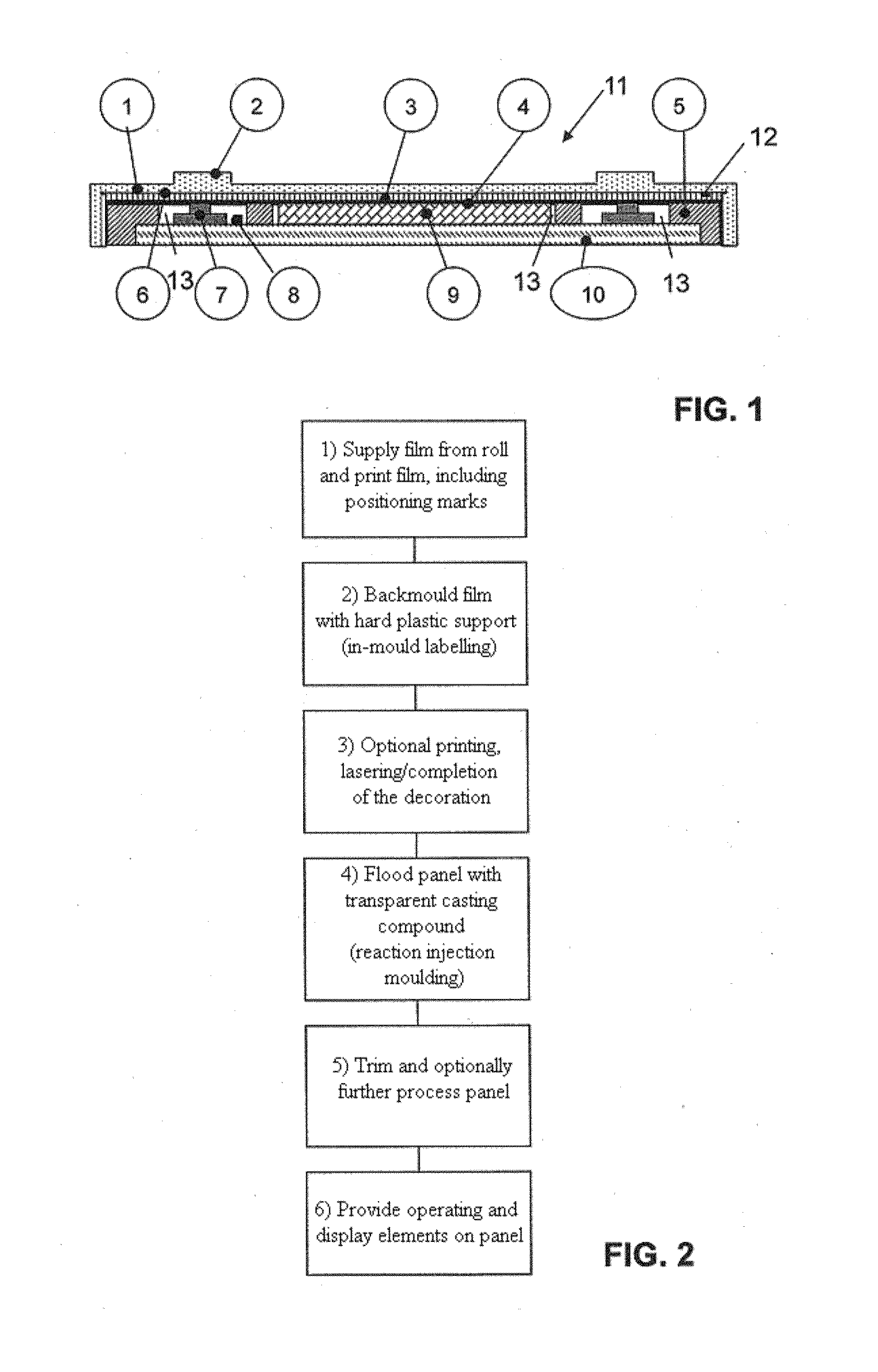
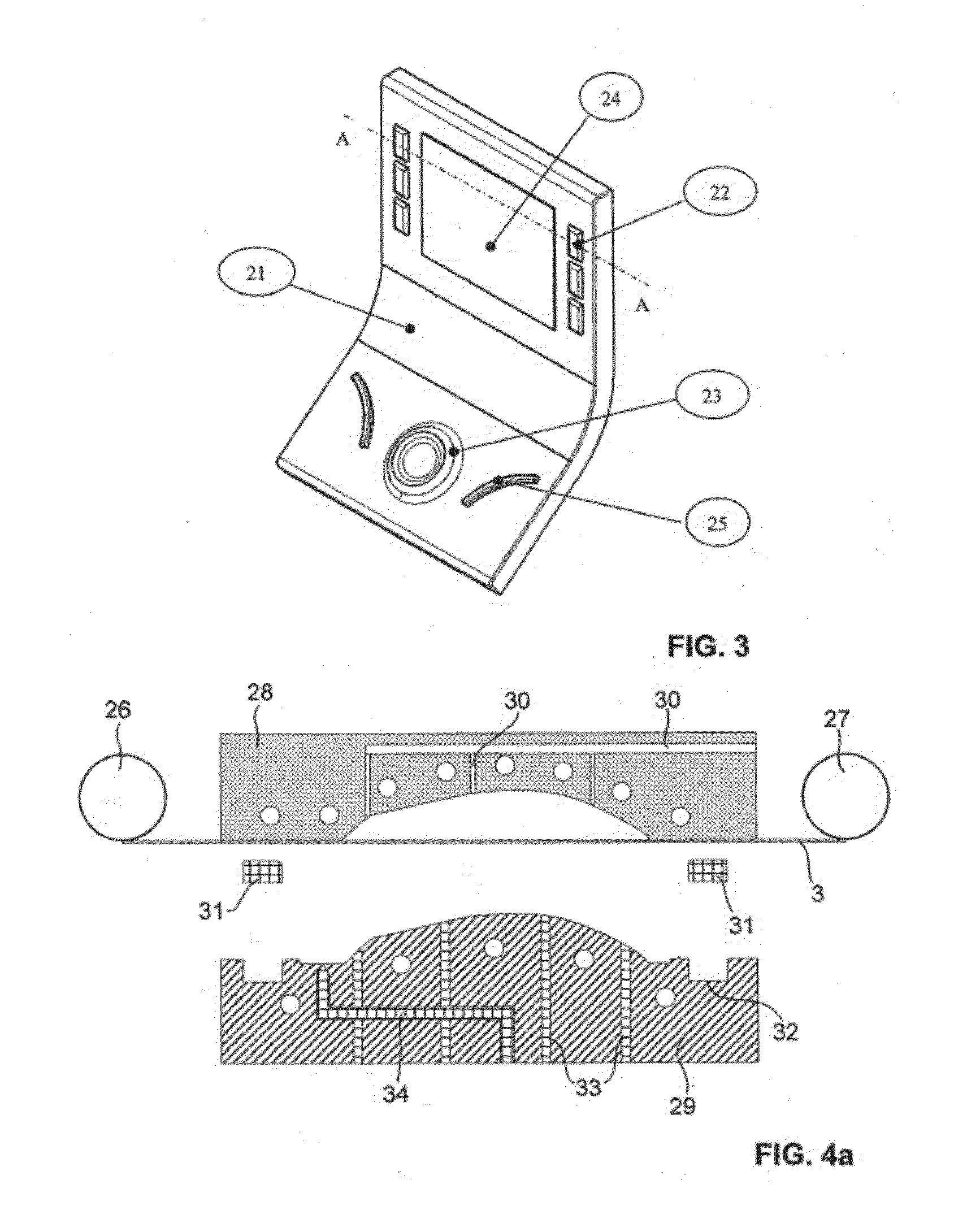
[0041]FIG. 3 shows an example of a panel of an automobile centre console, FIG. 1 shows a schematic section through such a functional support according to the invention along the line A-A of a construction according to FIG. 3, and FIG. 2 shows a representation of the individual process steps of the proposed process. Individual steps of this process are now to be explained as follows:

[0042]Step 1 from FIG. 2: The soft film 3 (for example TPU 200 μm thick) supplied from a roll is printed and decorated on the front and / or rear side, positioning marks 12 being additionally printed on. On the TPU roll, a positioning mark for each image is printed on respectively to the left and right in a black colour. To the left for the longitudinal alignment a square box, to the right for the lateral alignment an oblong bar. In the sectional representation according to FIG. 1, there is also in the finished component 11 the positioning mark 12, which is at a point where it is for example unproblematic f...


PUM

PropertyMeasurementUnit
thicknessaaaaaaaaaa
thicknessaaaaaaaaaa
thicknessaaaaaaaaaa

Abstract

A process for producing a multifunctional functional support in which operating elements or display elements are arranged. The process includes flexible transparent plastic film supplied from a roll; the flat plastic film is placed into an injection mold, and is backmolded to form a rigid support structure-on a first side, wherein in the region of the operating elements or display elements it remains exposed in the form of at least two clearances; on the second side the plastic film is flooded in the same injection mold with a transparent curing casting compound in an RIM process to form a transparent surface layer, membrane regions that are flexible at least in places being formed in the region of the clearances; operating elements or display elements are placed into the clearances and joined to the plastic support.

Description

CROSS-REFERENCE TO RELATED APPLICATION[0001]This application claims priority to Switzerland Patent Application No. 00942 / 13 filed May 13, 2013, the disclosure of which is hereby incorporated in its entirety by reference.BACKGROUND OF THE INVENTION[0002]1. Field of the Invention[0003]The present invention relates to a process for producing a multifunctional functional support, for example a console structure for a vehicle or a device, with a rigid support structure, in which operating elements and / or display elements are arranged behind a transparent surface layer which is continuous over substantially the entire functional support. The invention also relates to functional supports produced in this way.[0004]2. Description of Related Art[0005]Today, operating elements and display devices as well as buttons of all types are incorporated in automobile interiors in clearances in a large panel. This results in gaps and material transitions.[0006]The solutions known today can be summarize...

Claims


Application Information

Patent Timeline
Patent Type & Authority Applications(United States)
IPC IPC(8): B29C45/14F21V8/00
CPCG02B6/0081B29C45/14024B29C45/14008B29C45/0053B29C45/1418B29C45/14262B29C45/14311B29C45/14688B29C45/1671B29C2045/14131B29C2045/14155B29C2045/14696B29K2995/0026B29L2031/3443H01H13/88H01H2229/046H01H2229/047
Inventor KEIST, CHRISTOPHEHRIG, FRANKKEISER, SWENMARTY, DANIEL
Owner ABATEK INT
Why Eureka
Try Eureka