
Removing lead filter from serial multiple-stage filter used to detect large flows in order to purge flows for prolonged operation

a multi-stage filter and filtering technology, applied in the field of network detection, can solve the problems of reducing the ability of parallel multi-stage filters to detect large flows, prohibiting the number of different flows, and affecting the detection effect of large flows, so as to avoid discontinuities

Active Publication Date: 2015-01-15
TELEFON AB LM ERICSSON (PUBL)
View PDF16 Cites 34 Cited by
  • Summary
  • Abstract
  • Description
  • Claims
  • Application Information

AI Technical Summary

Benefits of technology

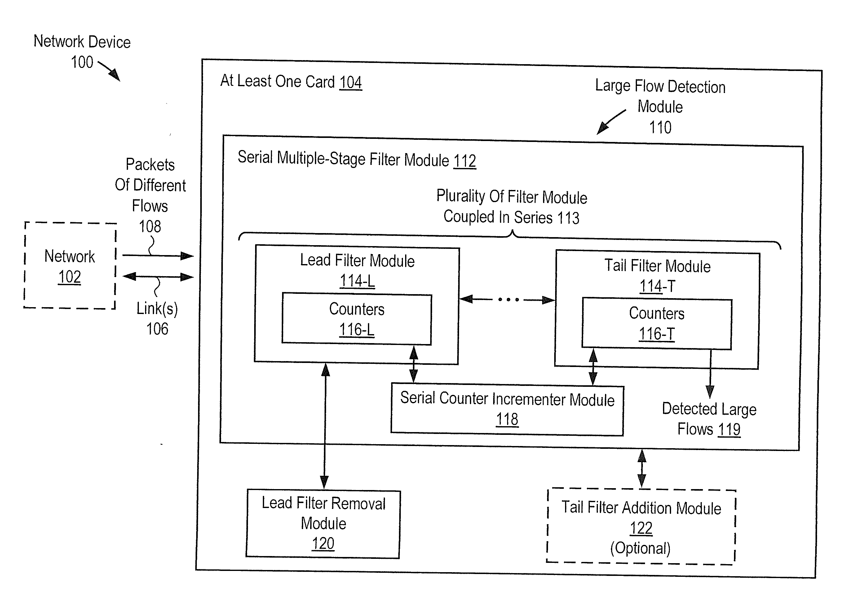
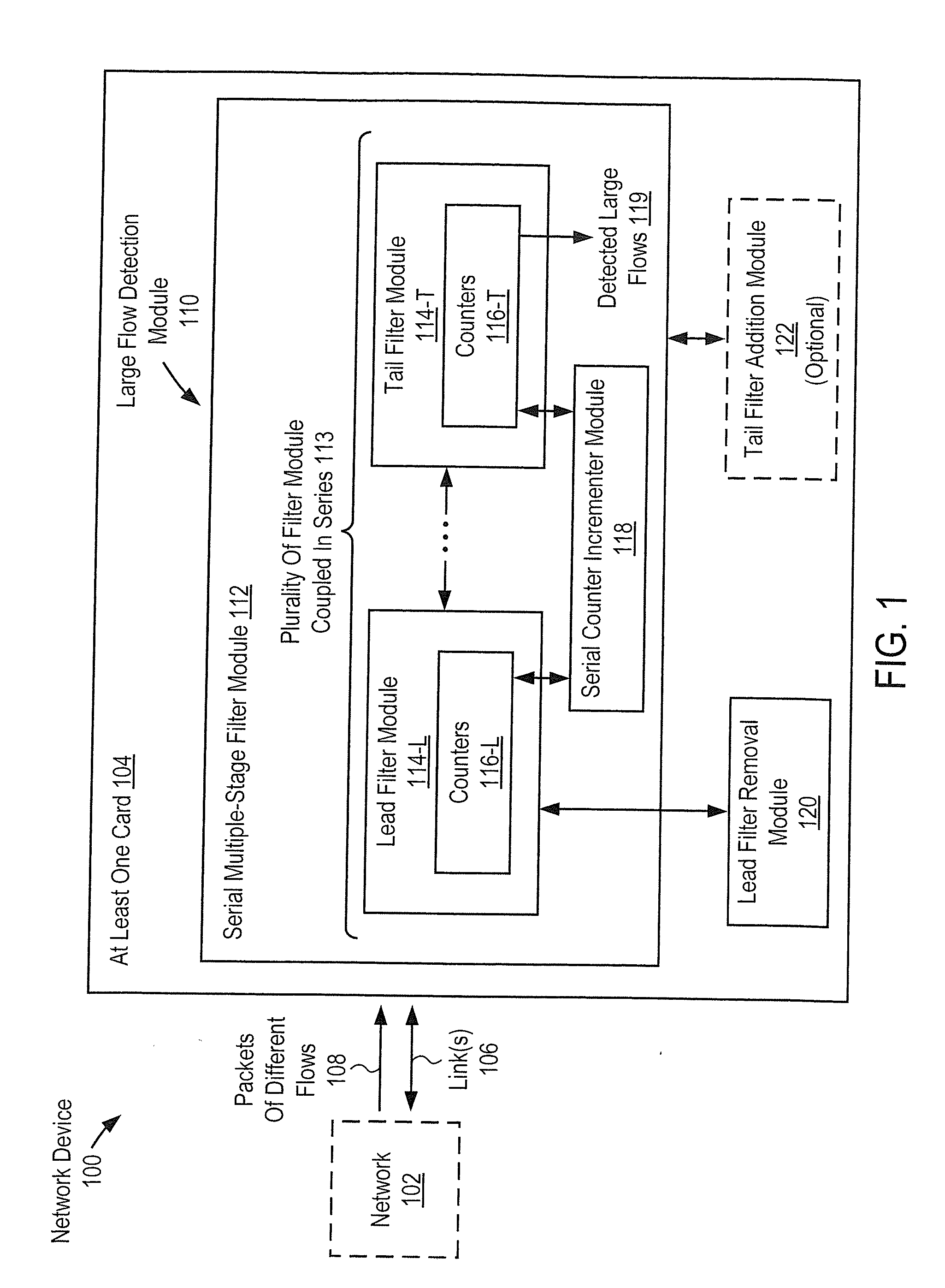
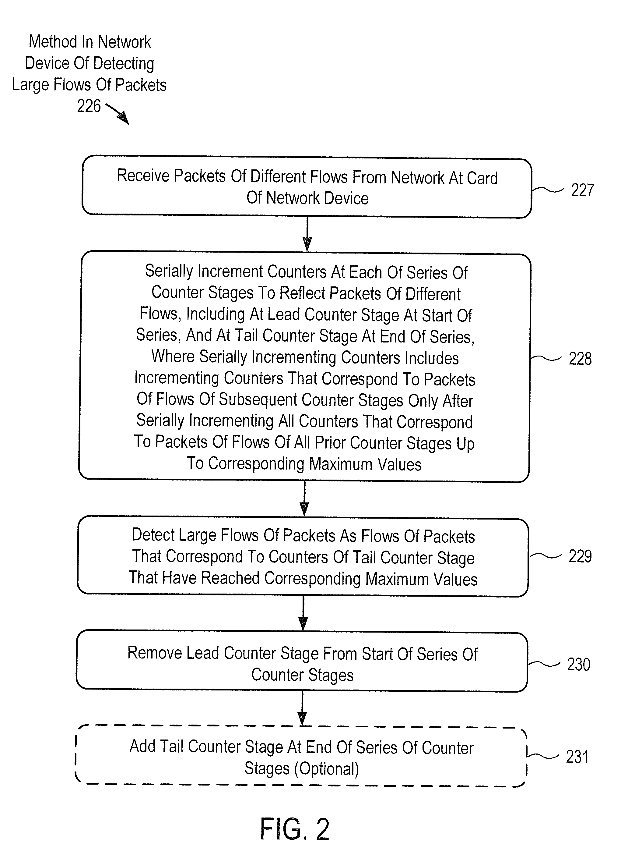
The patent describes a network device that can detect large flows of packets in a network. The device includes a large flow detection module that uses a serial multiple-stage filter module with counters to reflect the packets of different flows. The counters are incremented serially up to a maximum value for each module in the series. The device can also remove the lead filter module from the start of the series and add a new tail filter module at the end of the series during operation. The technical effect of this invention is the ability to purge accounting for flows over time and avoid discontinuities in large flow detection, which allows for continuous operation.

Problems solved by technology

Similarly, a large proportion of small flows often use only a small proportion of the overall bandwidth and other network resources.
However, often the number of different flows may be relatively large.
As a result, one possible drawback with such an approach is that including a counter for each different flow may tend to be prohibitive in terms of the amount of memory and memory access bandwidth resources needed to implement the relatively large number of counters.
However, one possible drawback with the parallel multistage filters discusses in this reference is that over time there tends to be a decrease in the ability of the parallel multistage filters to detect large flows.
However, this erasing or resetting of the counters tends to introduce a discontinuity in large flow detection and adds additional latency to large flow detection.

Method used


Image

  • Removing lead filter from serial multiple-stage filter used to detect large flows in order to purge flows for prolonged operation
  • Removing lead filter from serial multiple-stage filter used to detect large flows in order to purge flows for prolonged operation
  • Removing lead filter from serial multiple-stage filter used to detect large flows in order to purge flows for prolonged operation

Examples


Embodiment Construction

[0024]Described herein are methods and apparatus to remove lead filters from serial multiple-stage filters in order to purge records / accounting of flows and help allow prolonged large flow detection without discontinuity. In the following description, numerous specific details are set forth. For example, specific serial multiple-stage filters, filters, arrays of counters, orders of operations, logic partitioning / integration choices, and the like, and are set forth. However, it is understood that embodiments of the invention may be practiced without these specific details. In other instances, well-known circuits, structures and techniques have not been shown in detail in order not to obscure the understanding of this description.

[0025]FIG. 1 is a block diagram of an embodiment of a network device 100. As used herein, a network device (e.g., a router, switch, bridge) is a piece of networking equipment, including hardware and software, which communicatively interconnects other equipmen...


PUM


Abstract

A network device to detect large flows includes a card to receive packets of flows. The device includes a large flow detection module including a serial multiple-stage filter module including series filter modules including a lead filter module and a tail filter module. Each filter module includes counters. The serial filter module is to serially increment the counters to reflect the flows, and is to increment counters that correspond to flows of subsequent filter modules only after all counters that correspond to the flows of all prior filter modules have been incremented serially up to maximum values. The serial filter module is to detect flows that correspond to counters of the tail filter module that have been incremented up to maximum values as the large flows. The large flow detection module includes a lead filter removal module to remove the lead filter module from the start of the series.

Description

BACKGROUND[0001]1. Field[0002]Embodiments of the invention relate to the field of networking; and more specifically, to detecting large flows in networks.[0003]2. Background Information[0004]In many networks it is often the case that a small proportion of large flows use a disproportionately large proportion of the overall bandwidth and other network resources. These large flows are sometimes referred to as elephant flows or heavy hitter flows. Similarly, a large proportion of small flows often use only a small proportion of the overall bandwidth and other network resources. These small flows are sometimes referred to as mice flows. By way of example, in some networks, the largest 10% of the flows may use more than 80% of the bandwidth and other network resources.[0005]It is often desirable to be able to identify or detect such large flows so that they may be handled differently than small flows, or for various other purposes associated with network monitoring, network management, o...

Claims


Application Information

Patent Timeline
Patent Type & Authority Applications(United States)
IPC IPC(8): H04L12/801
CPCH04L47/10H04L43/022H04L43/028H04L43/00H04L47/11H04L45/00H04L47/2441H04L49/00H04L47/125H04L45/38H04L47/12H04L43/06H04L45/64H04L43/0888H04L43/16H04L43/20H04L43/08
Inventor BISHT, ASHUTOSHANAND, PRASHANT
Owner TELEFON AB LM ERICSSON (PUBL)
Learn More