Method of manufacturing continuous sucker rod

a technology manufacturing methods, applied in the direction of manufacturing tools, soldering devices,auxillary welding devices, etc., can solve the problems of increased costs associated with continuous sucker rods, increased production costs, and inability to meet the requirements of continuous sucker rods, so as to reduce space and time requirements, reduce capital costs, and eliminate heavy equipment

Inactive Publication Date: 2015-01-22
WEATHERFORD CANADA PARTNERSHIP
View PDF21 Cites 2 Cited by
  • Summary
  • Abstract
  • Description
  • Claims
  • Application Information

AI Technical Summary

Benefits of technology

The patent describes a method that eliminates the need for expensive equipment and reduces the space and time required, resulting in lower costs and a transferable facility.

Problems solved by technology

Each interconnection point between two successive conventional sucker rods is a source of potential weakness and excess wear on the adjacent tubing and casing.
However, increased costs can be associated with continuous sucker rod.
(The desired maximum diameter is limited by transport issues).
Oval cross-section sucker-rod is not suitable for rotating drive string applications due to the eccentric loads encountered during rotation and greater wear caused along the tubing.
Therefore, expensive oval cross-section continuous sucker rod, such as that disclosed by Palynchuk, is not generally used for rotary drive applications.
However, the hardness and corresponding tensile strength of the steel coils received from the mill in raw form is inconsistent, highly variable along individual coils and from coil to coil, and relatively low.
Input coils received from the steel mills in prior art practices are generally of very low hardness due to the chemistry and manufacturing processes used in the steel mill.
Without such treatment, the heat-affected zones would be a source of potential weakness which could cause failure of the continuous sucker rod in use.
These prior art methods of manufacturing continuous sucker rod therefore require extensive heavy, permanent equipment and a large fixed facility to practice the method within.
As a result, these prior art methods involve significant capital investment.
Such methods are disadvantageous in that they are highly labour intensive at remote locations.

Method used


Image

  • Method of manufacturing continuous sucker rod
  • Method of manufacturing continuous sucker rod
  • Method of manufacturing continuous sucker rod

Examples


Embodiment Construction

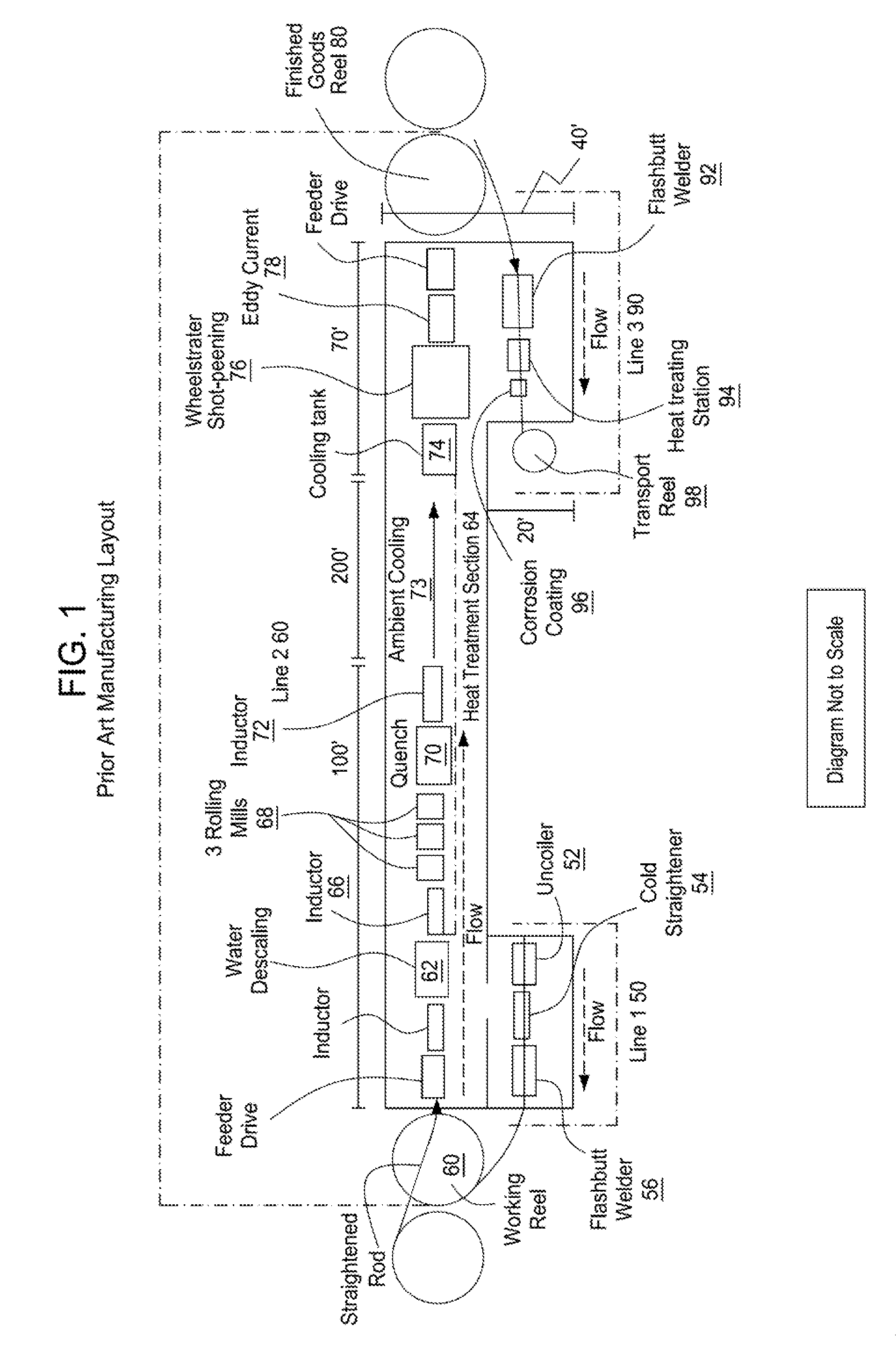
[0024]The prior art method shown in FIG. 1 is an illustration of the steps involved in a prior art method where the steel from the steel mill is selected without specifying a requirement of a uniform tensile strength along and among the input coils to be used to produce the continuous sucker rod. Referring now to FIG. 1, there are three lines in this method—Line 1 (50), Line 2 (60) and Line 3 (90).

[0025]On Line 1, the steel coil from the steel mill (not shown) is uncoiled by an uncoiler (52), then straightened by a straightener (54) and then passed through a first flash-butt welding section (56). Welding in the first flash-butt welding section (56) is applied only to the ends of the steel mill coils to fuse one end of one coil to the end of the next coil to form one continuous elongated piece of steel. After passing through the flash-butt section, the steel is transferred to a large working reel (58) to be held until production on Line 2 is initiated.

[0026]On Line 2 (60), the steel ...


PUM


Abstract

A method for manufacturing a continuous sucker rod coil, wherein the method includes the step of selecting a plurality of input coils, each input coil having the same uniform hardness, and each input coil having two free ends. The method further includes the step of fusing adjacent free ends of adjacent input coils together to form one continuous length of rod, the fusing creating fused areas and a heat-affected zone at each fused area. The method also includes the step of treating each of the heat-affected zones to alleviate irregularities induced during fusing. Additionally, the method includes the step of winding the continuous length of rod into a finished coil.

Description

CROSS-REFERENCE TO RELATED APPLICATIONS[0001]This application is a continuation of co-pending U.S. patent application Ser. No. 13 / 648,141, filed Oct. 9, 2012, which is a continuation of U.S. patent application Ser. No. 10 / 518,620, filed Jan. 20, 2006, now U.S. Pat. No. 8,281,472, which is a 371 of PCT / CA2003 / 000981, filed Jun. 27, 2003. The aforementioned applications are herein incorporated by reference.BACKGROUND OF THE INVENTION[0002]1. Field of the Invention[0003]This invention relates to a simplified method and apparatus for manufacturing continuous sucker rods.[0004]2. Description of the Related Art[0005]In oil and gas wells, a “drive string” connects the pump, located down hole, to the drive system, located at the surface. Conventional sucker rods are elongated steel rods, 20 feet to 30 feet in length. Traditional drive string typically consisted of a sequence of conventional sucker rods with connecting mechanisms at each end of each conventional sucker rod which permit end-t...

Claims


Application Information

Patent Timeline
Patent Type & Authority Applications(United States)
IPC IPC(8): B23Q41/06B21C43/04B23K37/00B23P23/06E21B17/00B21C51/00B21C47/24B21C37/04B21C43/02
CPCB23P23/06B23Q41/06B21C43/02B21C37/04B23K37/00B23K31/02B21C51/00B21C47/247B21C43/04B21C37/045E21B17/00Y10T29/49771Y10T29/49764Y10T29/49778Y10T29/5136
Inventor LABONTE, DAVIDGERELUK, RICKY
Owner WEATHERFORD CANADA PARTNERSHIP
Why Eureka
Try Eureka