Cleaning apparatus

a cleaning apparatus and cleaning technology, applied in the field of cleaning apparatuses, can solve the problems of difficult to discharge the and the cleaning fluid striking the sponge may become a mist, etc., to achieve the effect of easy absorbing by the sponge and low discharge rate of cleaning fluid absorbed by the spong

Active Publication Date: 2015-01-22
DISCO CORP
View PDF1 Cites 5 Cited by
  • Summary
  • Abstract
  • Description
  • Claims
  • Application Information

AI Technical Summary

Benefits of technology

[0005]A sponge is provided on an inner surface of the scatter prevention cover in the cleaning apparatus to absorb the cleaning fluid scattering from the holding table. Since the sponge has a three-dimensional network structure, the cleaning fluid can be easily absorbed by the sponge. However, the cleaning fluid absorbed by the sponge is hard to discharge. Accordingly, a rate of discharge of the cleaning fluid absorbed by the sponge is low, and when the sponge is saturated with the cleaning fluid, there arises a problem such that the cleaning fluid striking the sponge may become a mist, which may stick to a periphery of the wafer or the holding table.

Problems solved by technology

However, the cleaning fluid absorbed by the sponge is hard to discharge.
Accordingly, a rate of discharge of the cleaning fluid absorbed by the sponge is low, and when the sponge is saturated with the cleaning fluid, there arises a problem such that the cleaning fluid striking the sponge may become a mist, which may stick to a periphery of the wafer or the holding table.

Method used


Image

  • Cleaning apparatus
  • Cleaning apparatus
  • Cleaning apparatus

Examples


Embodiment Construction

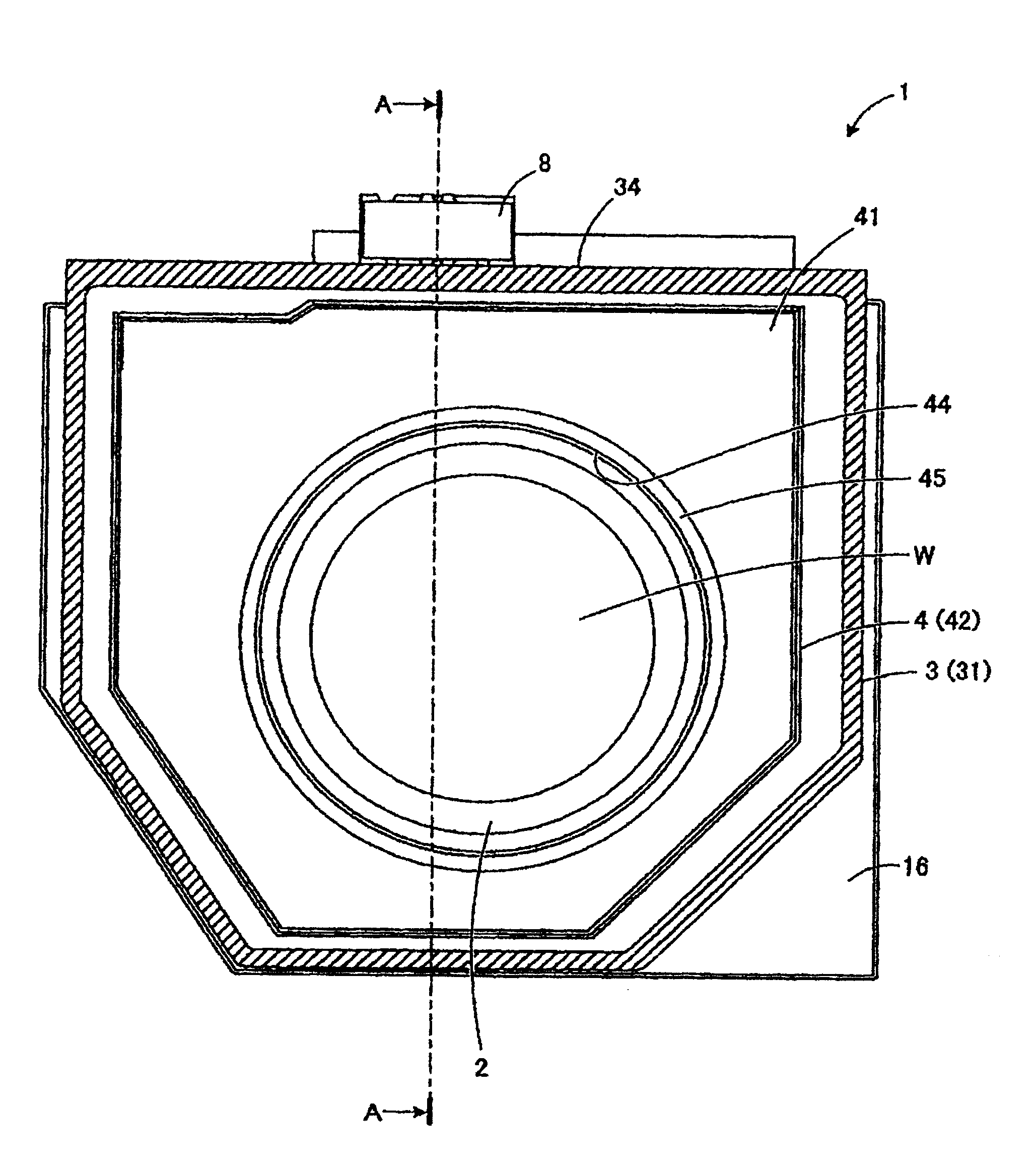
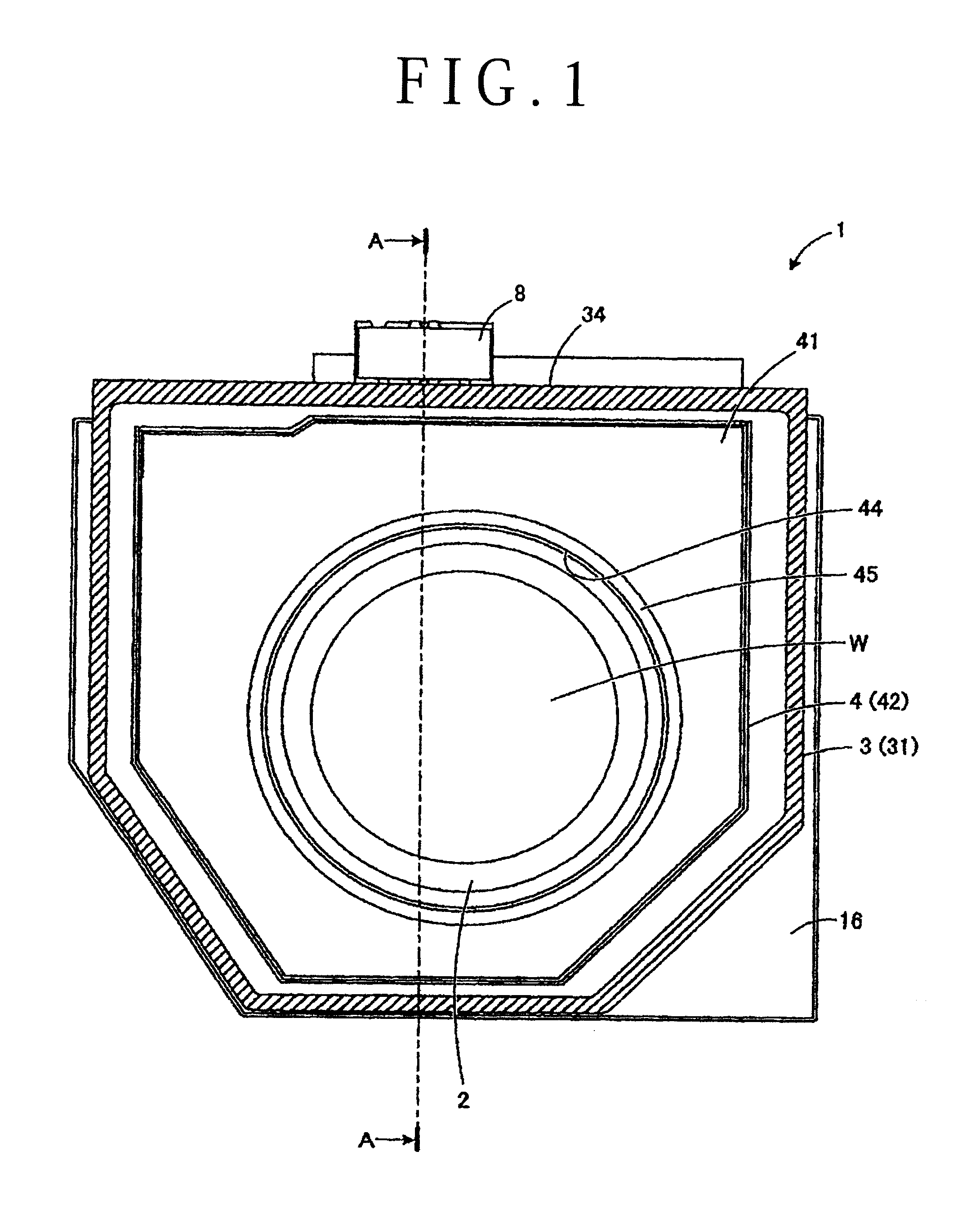
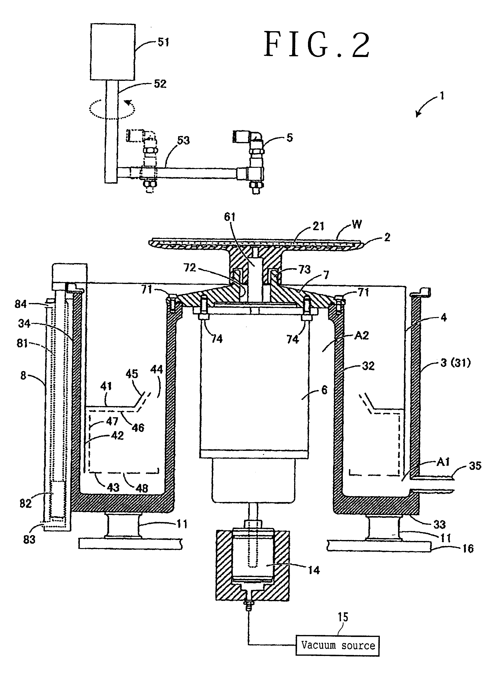
[0014]A preferred embodiment of the present invention will now be described in detail with reference to the attached drawings. FIG. 1 is a schematic top plan view of a cleaning apparatus 1 according to this preferred embodiment. FIG. 2 is a schematic sectional view of the cleaning apparatus 1 as taken along a line A-A in FIG. 1. A configuration of the cleaning apparatus 1 shown in FIG. 1 is merely illustrative and it may be suitably modified. In FIG. 1, a cleaning nozzle is not shown for convenience of illustration.

[0015]As shown in FIGS. 1 and 2, the cleaning apparatus 1 includes a holding table 2 for holding a plate-shaped workpiece W, a motor 6 for rotating the holding table 2, and a cleaning nozzle 5 for spraying a cleaning fluid to the plate-shaped workpiece W held on the holding table 2 during rotation of the holding table 2. The cleaning apparatus 1 is used for cleaning of the plate-shaped workpiece W after performing various kinds of processing such as grinding, polishing, e...


PUM


Abstract

A cleaning apparatus including a holding table for holding a plate-shaped workpiece, a cleaning nozzle for spraying a cleaning fluid to the plate-shaped workpiece, and a table cover for covering a circumference of the holding table. The table cover includes a top plate for covering an upper side of the holding table and a side plate for covering the circumference of the holding table. The table cover is provided with a netlike mesh sheet spaced from a lower surface of the top plate and another netlike mesh sheet spaced from an inner surface of the side plate.

Description

BACKGROUND OF THE INVENTION[0001]1. Field of the Invention[0002]The present invention relates to a cleaning apparatus for cleaning a surface of a plate-shaped workpiece such as a semiconductor wafer.[0003]2. Description of the Related Art[0004]Conventionally known is a spinner type cleaning apparatus including a rotatable holding table for holding a wafer and a cleaning nozzle for spraying a cleaning fluid to the wafer held on the holding table being rotated (see Japanese Patent Laid-Open No. 2009-094247, for example). In the cleaning apparatus described in Japanese Patent Laid-Open No. 2009-094247, the cleaning nozzle is pivotally oscillated above the holding table in spraying the cleaning fluid from the cleaning nozzle to the wafer, thereby cleaning off soil sticking to the whole surface of the wafer. Since the cleaning fluid is sprayed to the wafer being rotated, the cleaning fluid on the wafer is scattered by a centrifugal force. To cope with this scattering of the cleaning flui...

Claims


Application Information

Patent Timeline
Patent Type & Authority Applications(United States)
IPC IPC(8): H01L21/67
CPCH01L21/67051H01L21/6838H01L21/68792
Inventor MAEJIMA, MAKOTO
Owner DISCO CORP
Why Eureka
Try Eureka